IRD-2600 / IRD-2800
Integrated Receiver Decoders
P/N 2349-72784-00 Page 2-9
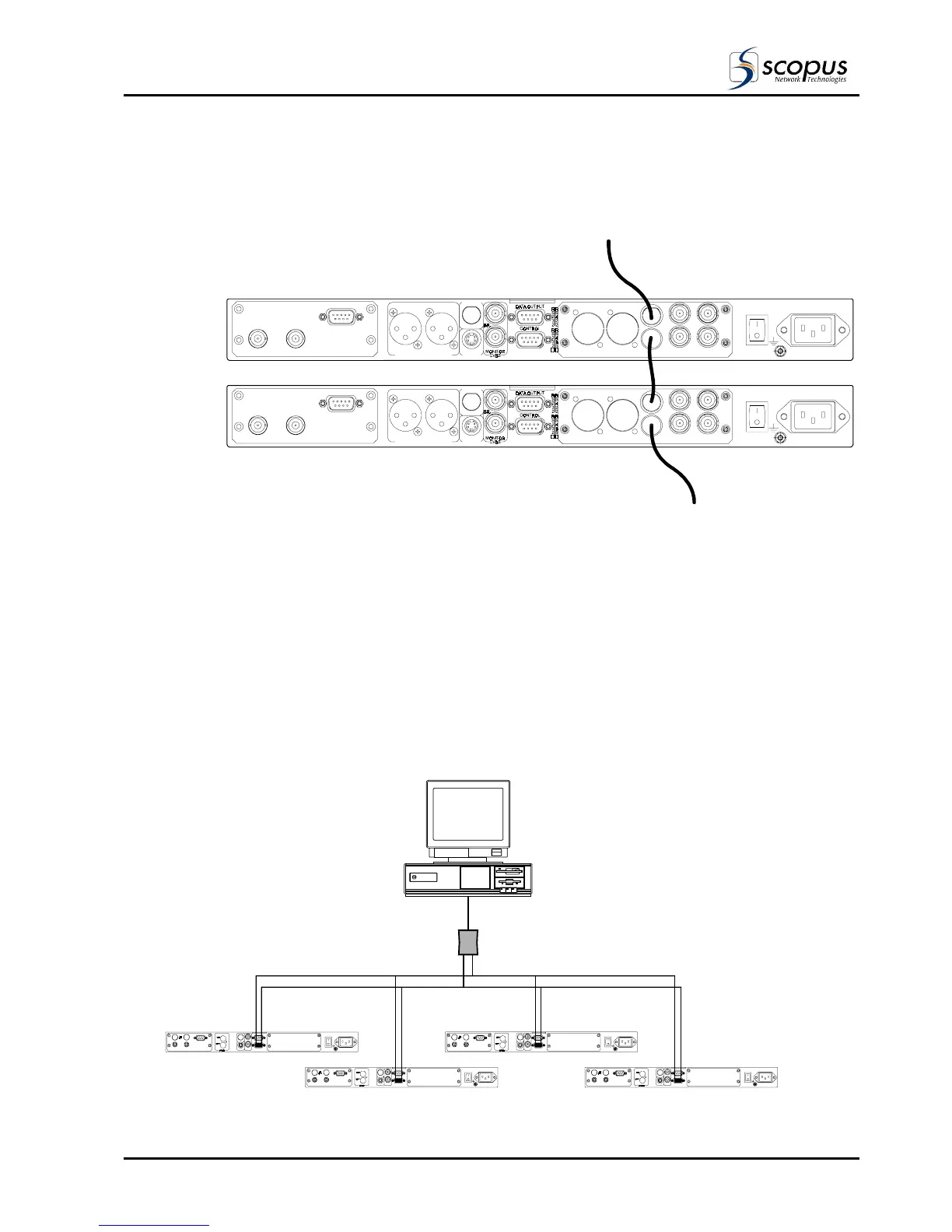
2.5.2. ASI Loopthrough Cascade
Connect the input signal to the bottom IRD ASI input (BNC). Cascade the remaining units as
shown in Figure 2-6.
Figure 2-6: IRD Cascade with ASI Loopthrough
[]
[]
LEFT2
AES/EB U1
[]
[]
RIGH T2
AES/EB U2
BALANCED AUDIO ASI SYNC LOCK SDI OUT
OUT
3
OUT 1
IN IN 2
100-240VAC 1A
50/60 Hz
LEFT1 RIGHT1
ANALOG AUDIO OUT
AES/EBU
AC3
S-VIDEO
ASI SOURCE
[]
[]
LEFT2
AES/EB U1
[]
[]
RIGH T2
AES/EB U2
BALANCED AUDIO ASI SYNC LOCK SDI OUT
OUT
3
OUT 1
IN IN 2
100-240VAC 1A
50/60 Hz
LEFT1 RIGHT1
ANALOG AUDIO OUT
AES/EBU
AC3
S-VIDEO
RS422/GPI
UNBALANCED
G703 INPUT LOOPTHROUGH
OUTPUT
DS3[ ] E3[ ] E2[ ] E1[ ]
RS422/GPI
UNBALANCED
G703 INPUT LOOPTHROUGH
OUTPUT
DS3[ ] E3[ ] E2[ ] E1[ ]
2.5.3. RS-485 Master-Slave Connection
Multiple IRD devices can be managed from a single terminal control station using a Master
Slave configuration as shown in Figure 2-7. As shown the Master-Slave configuration uses a
RS-232 to RS-485 converter. The converter is connected to a bus, which is in turn connected
to the IRD devices. The bus is comprised from transmit (Tx) and receive (Rx) route. Each
IRD device is identified on the bus by a unique address. All IRDs on the bus will receive Tx
and Rx messages, only the IRD with the matching address will respond to the command of
the Terminal.
Operation instructions for the Master-Slave Terminal Control Protocol can be found in the
IRD-2600/2800 Master-Slave Operation Guide.
Figure 2-7: Master-Slave RS-485 Control Cable Configuration
RS 232
Tx
Rx
Tx Rx
RS 485
IRD 1
IRD 2
IRD 3
IRD 4