A01350693 Rev:P ECO: 7476 Date: 04/14/08 15
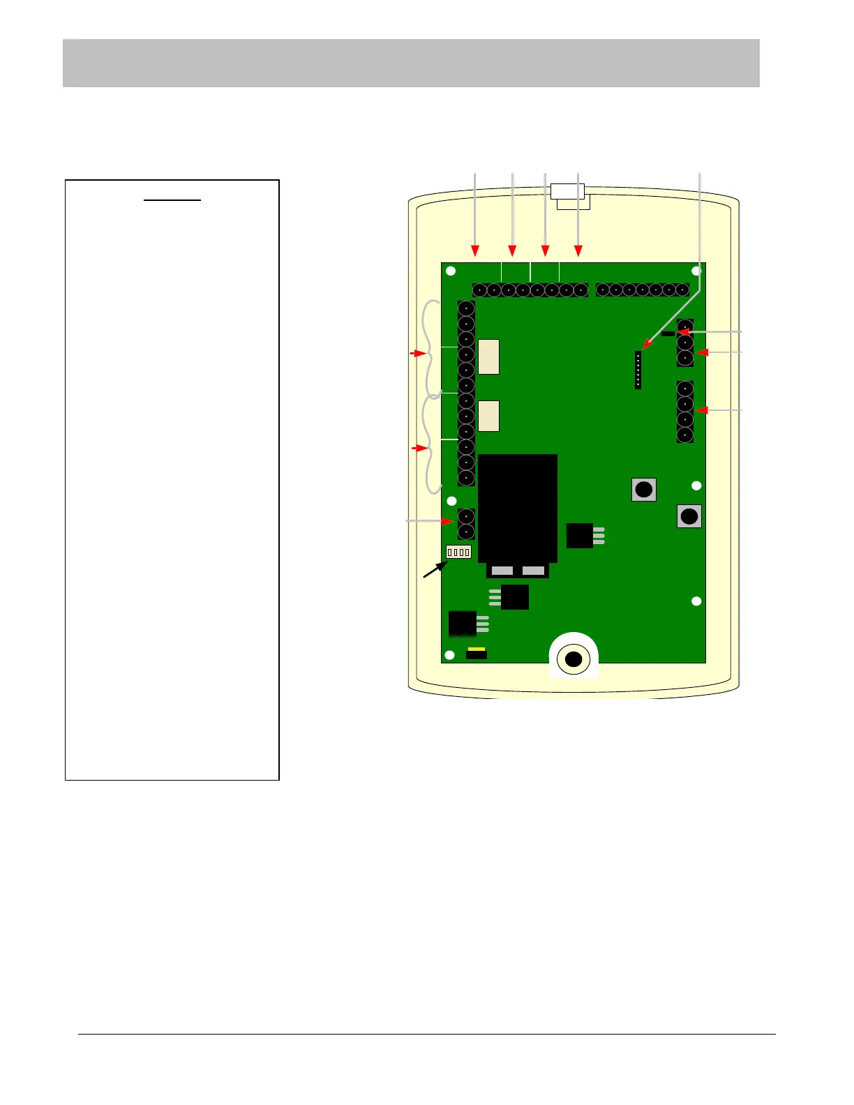
Figure 6-2 Rear View of 135DE Exit Panel
SECTION 6 SYSTEM COMPONENT DESCRIPTIONS
LEGEND
1. Electromagnetic lock Delayed
Egress connection
2. Normally Closed door contact
connection
3. Momentary Push Button or
Non-latching Key Switch
4. Fire alarm Normally Open dry
alarm relay connection (field
selectable)
5. Controlled area network (CAN)
connection
6. Remote Internal/External
Keypad connection (seven pin)
7. Electromagnetic lock relays ,
one and two connections
8. Auxiliary relays (one and two
connections)
9. DC power input connections.
10. CAN Bus termination jumper
11. External Model 135Receiver
connection. See Appendix D at
the end of this manual.
12. Dipswitches Power/Volume
FIRE PUSH DOOR EGRESS
LOCK AUX
CAN
L
CANHGND
SECURE CARE PRODUCTS
AUXLOCK
- +
NO C NC NO C NC NO C NC NO C NC
- +
KEYPAD
O N
1 2 3 4
1 2 3 4 5 6 7
1 2 3 4
2341
6
7
8
9
5
12
10
1- Power
2- Mute
3-Loud/Soft
4- Not Used
11