A01350693 Rev:P ECO: 7476 Date: 04/14/08 27
Each A02030901 (A02040901) Nurse Station Annunciator has a series of LED’s located on the front of the panel and a
Form C relay that will change state when any of the four channels alarm. There is a green LED and a red LED for each
device position. When the connected device is in a stand-by mode, the green LED will be illuminated and no sound will be
present. If a connected device is in an alarm condition, the red LED will begin to flash and an audible sound will be
present. This alarm condition on the A02030901 (A02040901) Nurse Station Annunciator will remain active until the field
device is reset and the condition satisfied. A place for labeling the field device is located between the LED’s and the piezo
sounders. This label should closely identify the device connected to that position.
Secure Care Software to XIU Connection
Secure Care Software provides central monitoring of the Secure Care Product’s security devices installed in a facility. The software
runs on ordinary Windows-based personal computers. Secure Care Software shows all activities on detailed floormaps of the facility.
Device images on a floormap are mapped to the devices they represent so that Secure Care Software can manipulate the image in
response to events and status changes involving the device.
The software receives communications from field installed devices via a communication hub device known as an “XIU”. The XIU
(discussed later in this section) provides two-way communication to and from field devices using an RS-485 architecture. This
architecture will be referred to the “CAN bus” throughout this Manual. The CAN bus will be discussed in further detail in the XIU
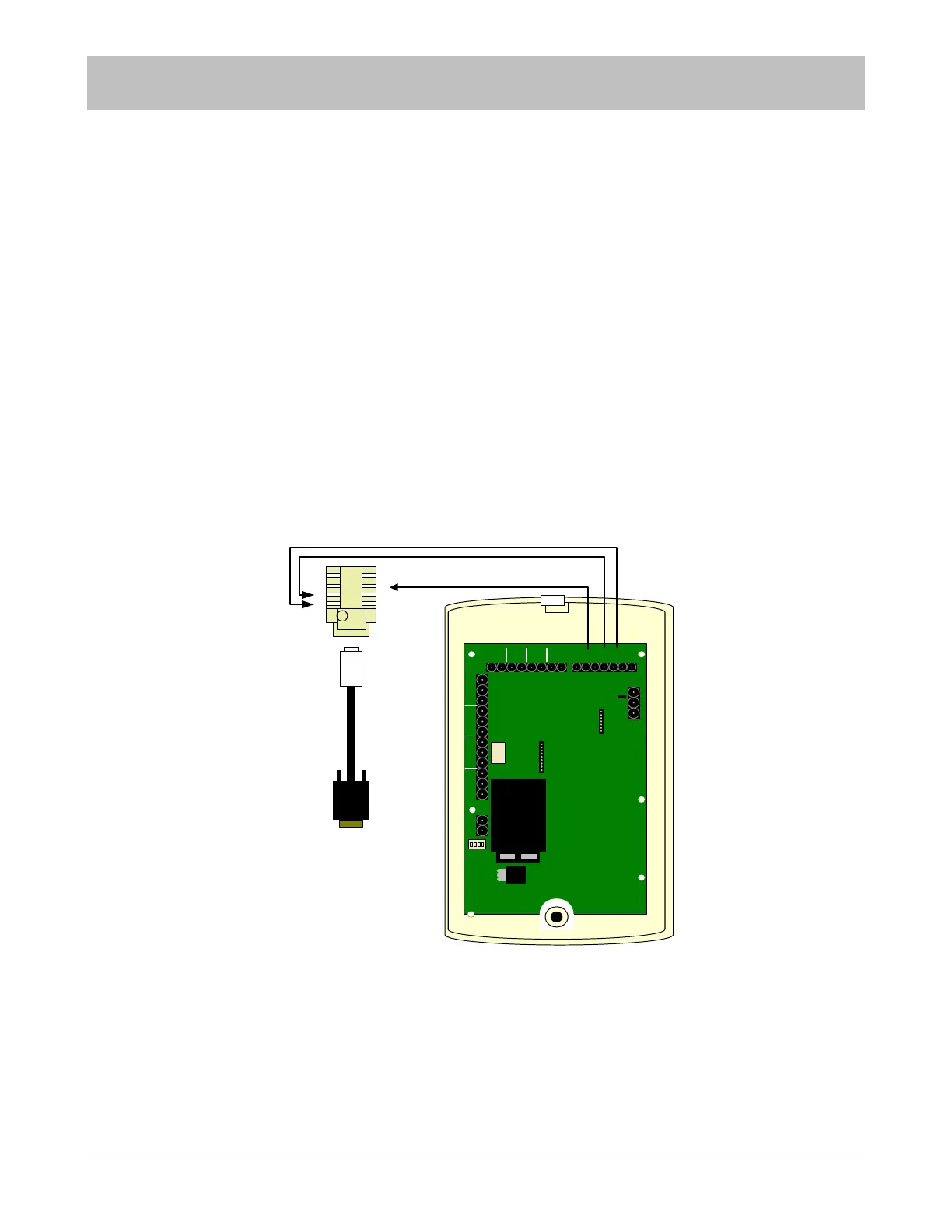
section of this manual. The XIU should be connected to the COM port on the back of the computer loaded with the SCP Software.
To make the connections to the XIU connect the ORANGE wire coming from the exits to the screw terminal marked CANH.
Connect the BLUE wire to the screw terminal marked CANL, and last connect the ground wire to the screw terminal mark GND.
FIRE
PUSH
DOOR EGRESS
AUX
CANLCANHGND
SECURE CARE
PRODUCTS
LOCK
- +
NO C NC
- +
KEYPAD
O
N
1 2 3 4
1 2
3
4
5
6
7
1) POWER
2) NOT USED
3) NOT USED
4) NOT USED
LOCK
NO C NC
AUX
NO C NC NO C NC
CAT5
U
L
1
2
3
RJ4
5
EN
D
DATA IN
DATA OUT
GROUND
4
5
6
7
8
TAB DOWN
Custom Made Cable included in
the Computer Package.
CAT 5 XIU
JACK
.
1 TO 3
2 TO 4
3 TO 6
Figure 9-6 XIU to Computer Connection
To make the connections to the computer connect the ORANGE wire to pin 3 on the back of the XIU and pin 1 on the RJ 45 jack.
Connect the BLUE wire to pin 4 on the back of the XIU and pin 2 on the RJ 45 jack. Connect the BLUE/WHITE wire to pin 6 on
the back of the XIU and pin 3 of the RJ 45 jack. For the XIU to computer/software connection, use the bank of seven screw
terminals. The connection between the RJ 45 jack and the computer COM ports is made with the custom made cable provided in
SCP Part #821 Computer Cable Kit.
SECTION 9 INST
LLATION AND CONNECTIONS