A01350693 Rev:P ECO: 7476 Date: 04/14/08 9
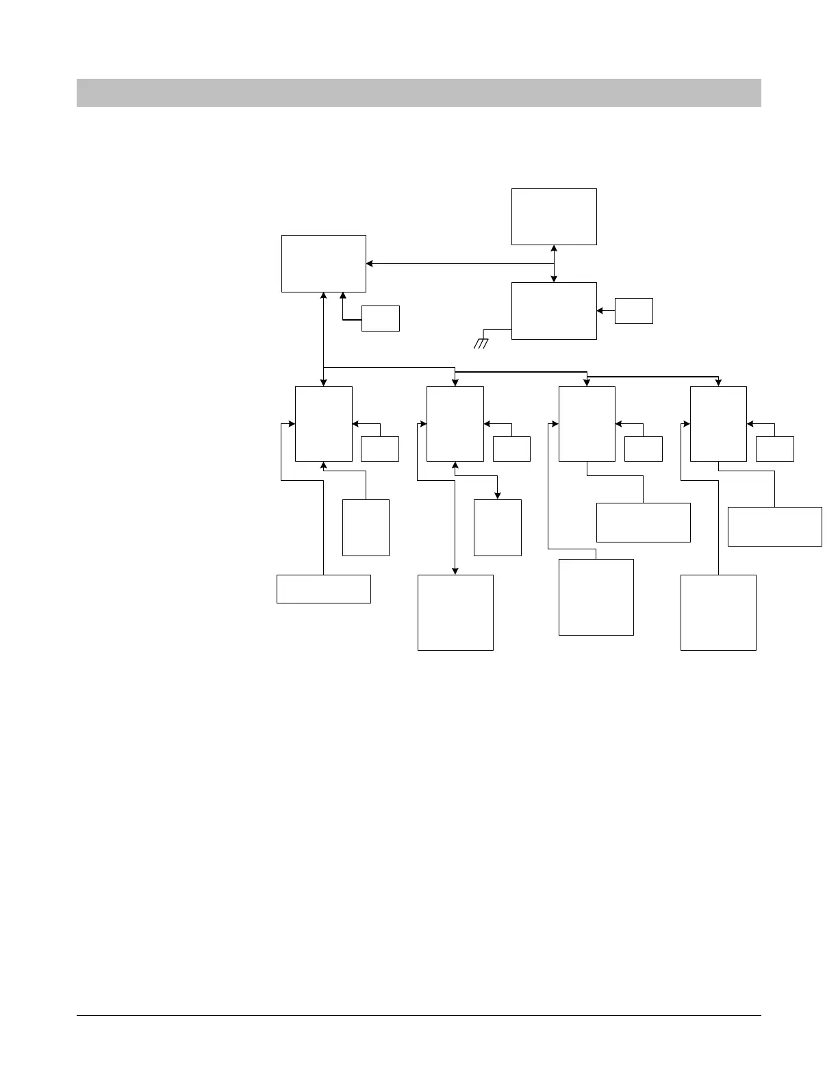
SECTION 2 SYSTEM BLOCK DIAGRAM
PERSONAL
COMPUTER
WITH
SECURE CARE
SOFTWARE
XIU
135 135 500DE
MAGNETIC LOCK
ELEVATOR
CONTROL
(135 and 135DE
only)
FIRE ALARM
CONTROL
Connection
required for any
device with
magnetic door lock.
EXTERNAL
ANTENNA
(135 and 135DE only)
EXTERNAL
KEYPAD
NURSE
STATION
PUSH
BUTTON
135DE
POWER
SUPPLY
POWER
SUPPLY
POWER
SUPPLY
POWER
SUPPLY
or
RS232 one way to Nurse Station or
Secure Care Software
Earth ground
connection at J1
position "F"
POWER
SUPPLY
Bi-directional CAN (Controller Area Network) communications bus. Maximum 94 devices connected to XIU.
MAGNETIC LOCK
FIRE ALARM
CONTROL
Connection
required for any
device with
magnetic door lock.
SUPPLY
POWER
A01350691, Rev. A
Fig. 2
Figure 2-1 System Block Diagram
NOTE: This diagram is UL required. Do not remove or change Part Number or Figure #.