A01350693 Rev:P ECO: 7476 Date: 04/14/08 25
Surface Mount Enclosure (ID Nurse Station Console, A02040901 LED Nurse Station Annunciator)
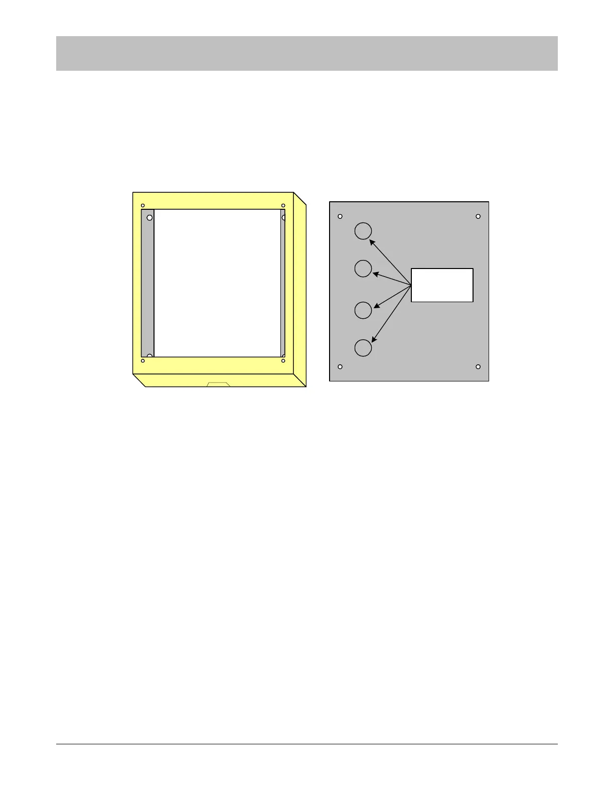
This surface mount enclosure should be mounted in a convenient location for monitoring by facility staff. It mounts easily using
the Madison clips provided. Knockouts for wire entry are available in all four sides and back of the enclosure. Wiring may be
routed through one or more of the six provided knockout locations or through surface mounted non-metallic conduit into the
knockouts on the top or bottom of the enclosure. Use the strain relief cable clamps provided for wire entry.
Figure 9-4 Surface Mount Enclosure for Nurse Stations
Use the backplate as a template and mark four mounting holes. Drill a ¼” hole for each anchor location and install the plastic
anchors provided. Apply the strain relief connector to required knockout locations. Route the wires through strain relief connector.
A maximum of six wires may be pulled through each ½” cable clamp. Tighten the strain relief connector around the wires. The
wires should withstand 35 pounds of pull force without slipping through the connector. Use the #10 X 1” stainless steel, pan head,
sheet metal screws provided to mount the enclosure and backplate to the wall. (Note orientation of backplate).
NOTE: Strain relief of routed cables is required to retain UL product listing. If above
instructions are not followed, product listing is subject to removal.
SECTION 9 INSTALLATION AND CONNECTIONS
top
1/2" knockouts
for strain relief
connectors