A01350693 Rev:P ECO: 7476 Date: 04/14/08 19
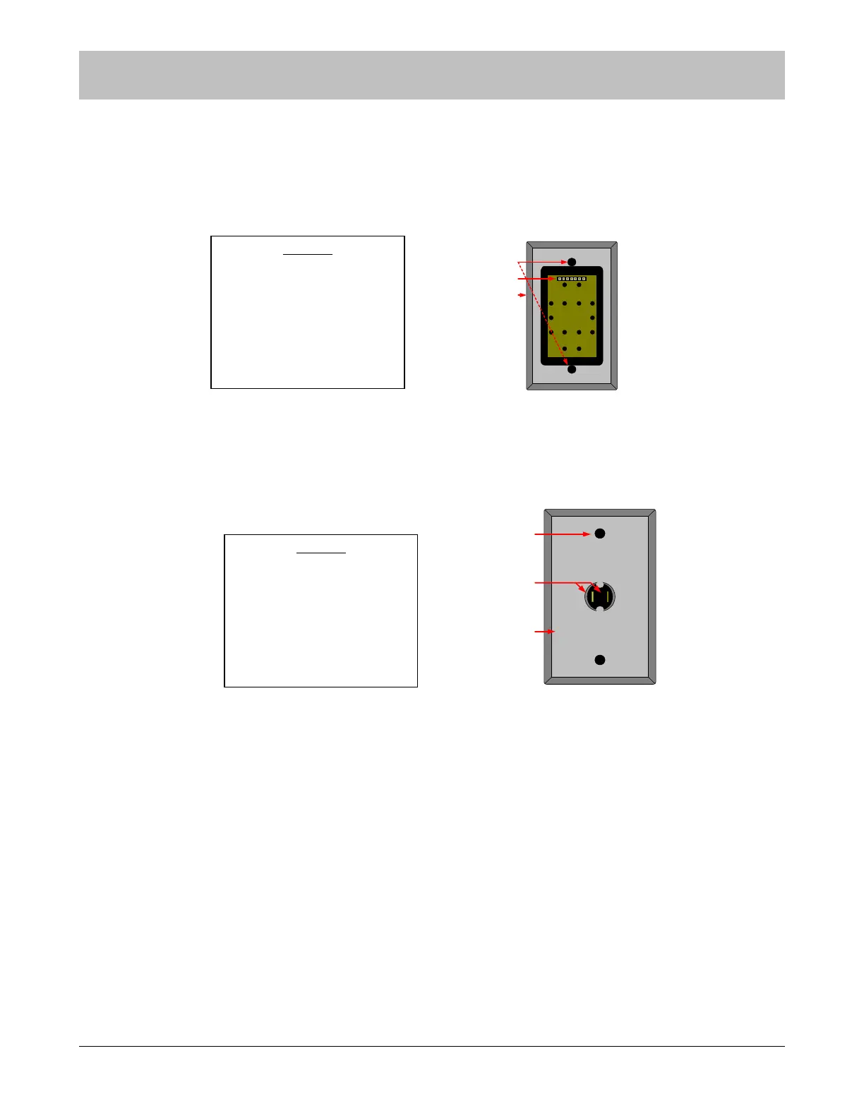
Indoor/Outdoor Remote Keypad Layout
Figure 6-7 Rear View of Remote Keypad
Indoor/Outdoor (N/O) Push Button Layout
Figure 6-8 Rear View of Push Button
SECTION 6 SYSTEM COMPONENT DESCRIPTIONS
1
2
3
LEGEND
1. Mounting screw holes
2. Seven pin connector for seven
conductor ribbon cable
3. Steel faceplate
LEGEND
1. Mounting screw holes
2. Spade lug terminal
connectors (Normally Open –
Activated Closed)
3. Steel Faceplate
1
2
3