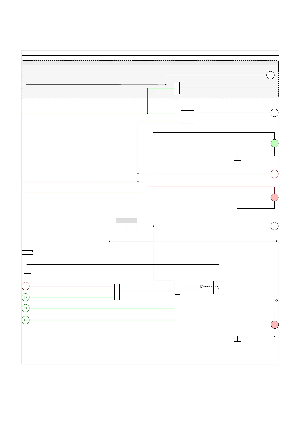
4.1.1.1 Trip Pulse and WIC1 LEDs
Trip command
wiProtGeneral_Y07
Output “TC−”
COM
✕
&
Energy Storage TC
(trip coil)
Output “TC+”
52
Prot . TripCmd
1
System . Prot. Ready
(Device has enough energy for trip pulse)
53
Backup Protection . Trip command
≥1
COM
✕
≥1
49
Prot . Pickup
51
Prot . Trip
LED “Ready”
LED “Pickup/Trip”
Only if: Device = WIC1-4
The device is supplied by external auxiliary power.
Prot . Syst. O.K. & Ext.Suppl.
&
S1 1
R 1
18
Prot . Active
3
Device is externally supplied
SW-based protection non-functioning
✕
4
“Error”
Please Refer To Diagram: wiBackupPOC_Y01, Backup Protection
≥ 24 V
SW-based protection is active
Operating Mode “Protection-Only”
≥1
LED “Error”
COM
Fig. 40: WIC1 LEDs and Trip pulse.
Note that the trip pulse is output like shown in the diagram, by connecting the “TC−”
contact internally with COM. A detailed description of the WIC1 LEDs can be found in ╚═▷
“3.8.1 LEDs”.
124 WIC1 WIC1-1.0-EN-MAN
4 Protective Elements
4.1.1.1 Trip Pulse and WIC1 LEDs

 Loading...

