7.1.3
Measurement of the Resistive Burden
The commissioning often involves measuring the resistive burden at the current inputs, so
that the impedance on the secondary side is known.
• One method is to disconnect all wirings between the CTs and the WIC1, so that all•
the resistances can be measured.
• Another method is to disconnect only the WIC1 current measuring inputs and•
measure the total resistance (i. e. forward wire + CT winding resistance + back wire).
In this case it is helpful to know the CT winding resistance in advance. For the
construction type 2, the values are listed in the Technical Data.
7.1.4
Checks During Commissioning
When putting into operation, the wiring and setting of the protection relay should be
checked. Here the person doing the commissioning work is assisted by the integrated test
windings of the WIC1 protection system, which are on the front of the relay. Hence any wiring
jobs as well as actions in the cable connection area can be disregarded.
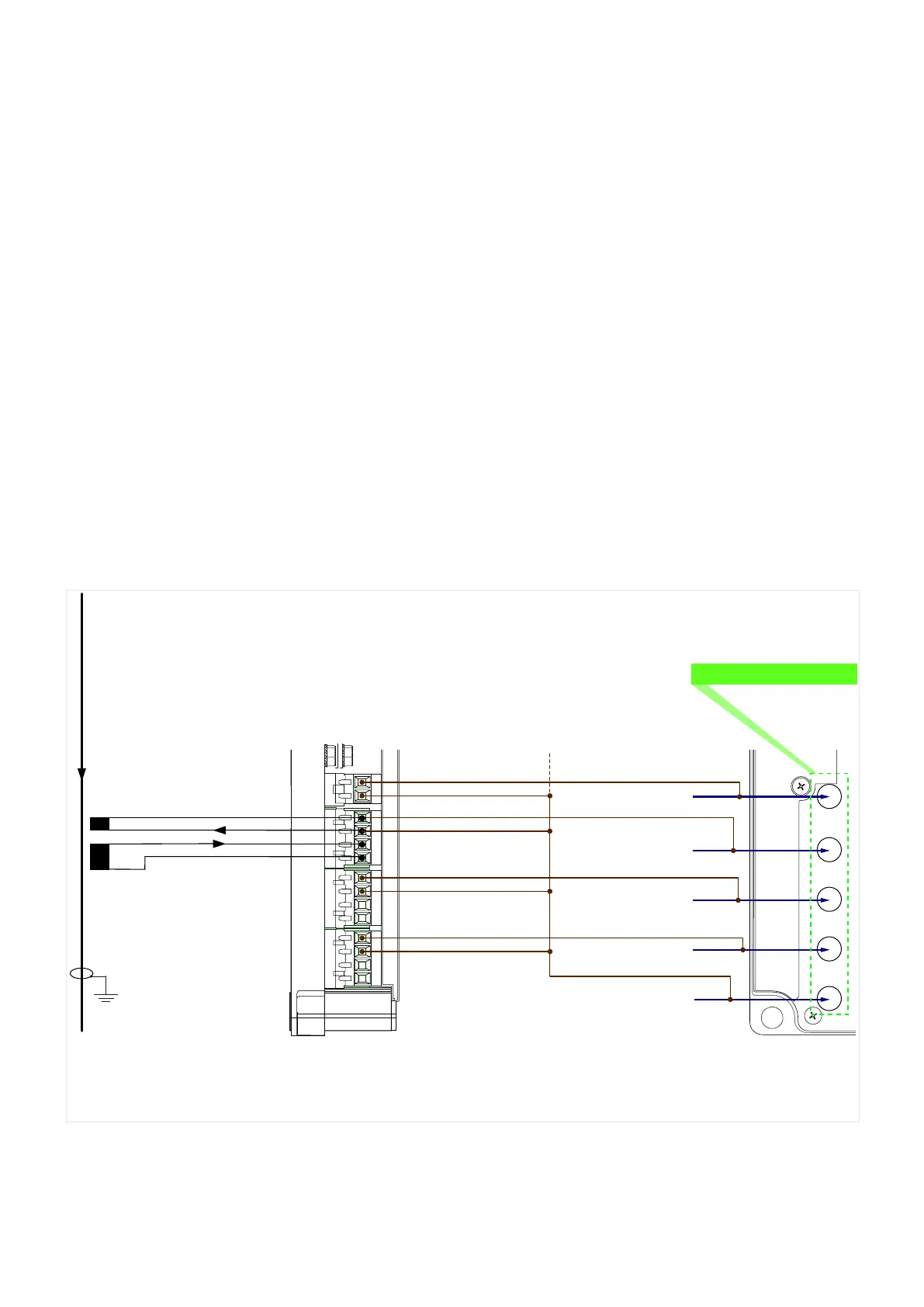
7.1.4.1 Test Windings, Test Sockets
COM
I test, IG
I test, L2
I test, L3
I test
Front View
Side View
WIC1
WIC1_Z32
L1
Meas. Winding
Test Winding
Device-Internal Connections
1 A
WIC1
Test Sockets
1S1
1S2
C
D
Fig. 68: Test windings and the device-internal connections to the test sockets. (CT connections
only for phase L1 shown.)
The WIC1 uses special CTs (see ╚═▷ “2.6.1.3 Order Form of the WIC1-Compatible Current
Transformers”, ╚═▷ “3.3.2 Selection of a WIC1-Compatible Current Transformer”), with a
secondary current that is dierent from the common values 1 A and 5 A. Therefore it is not
possible to perform exactly the same tests using the same 1 A / 5 A-testing devices, as with
protection devices that are designed for standard CTs.
190 WIC1 WIC1-1.0-EN-MAN
7 Commissioning
7.1.3 Measurement of the Resistive Burden

 Loading...

