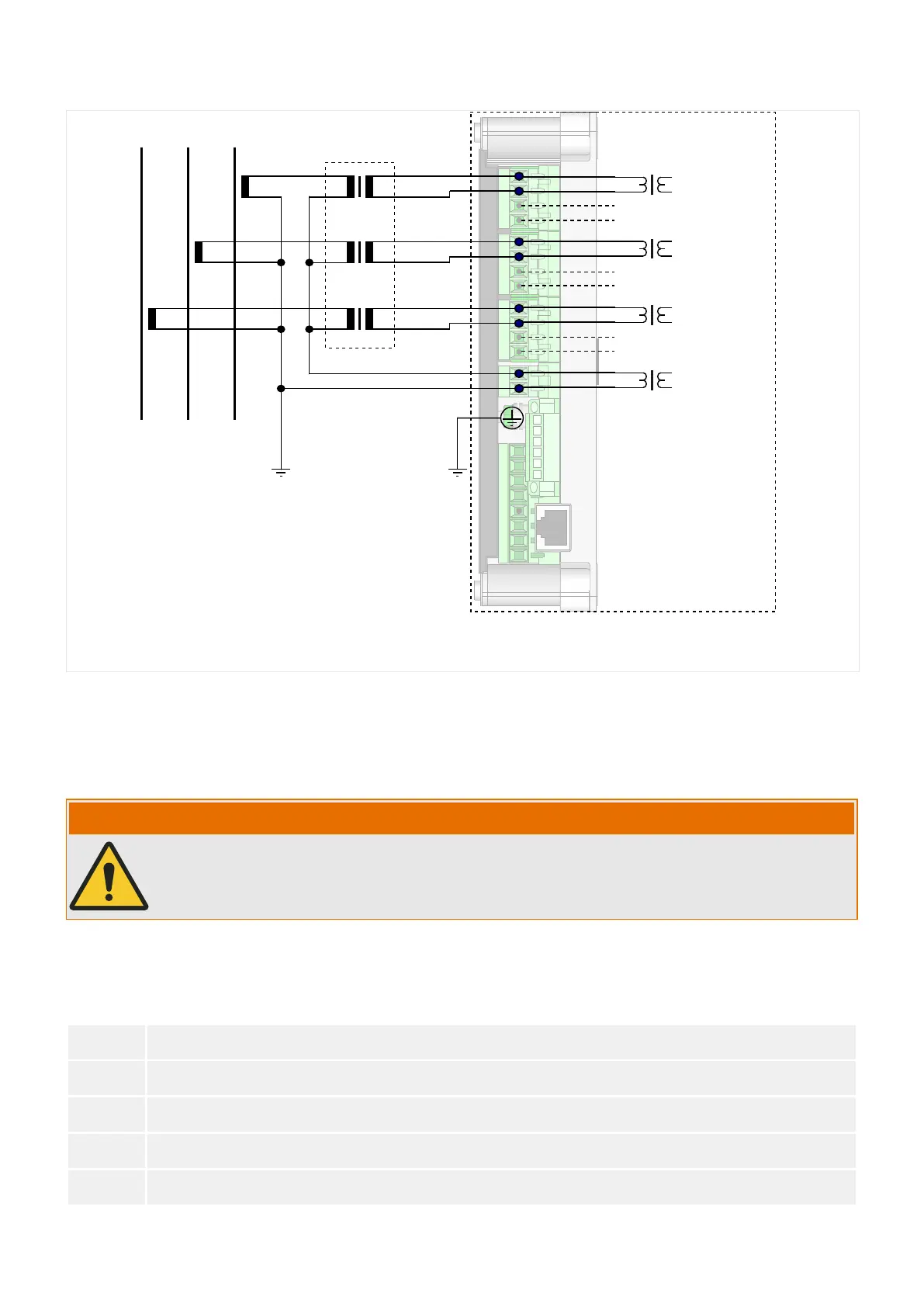
IL1,sec
IL2,sec
IL3,sec
(internal)
C
D
C
D
C
D
not connected
PE
Standard CTs, 1 A
not connected
not connected
IG,sec
E2
E1
Adapter CTs
Fig. 21: Connection of 1 A standard CTs with adapter CTs in a Holmgreen circuit.
The 1 A standard CTs, however, must fulll some requirements so that the WIC1 can be
safely supplied and the current can be measured with sucient accuracy.
3.3.3.1
Requirements for 1 A Standard CTs being Used with Adapter CTs
WARNING!
In addition to the considerations in this chapter and the requirements mentioned, all
applicable national and international standards and regulations have to be followed.
Symbols
The following table gives an overview of the symbols that are used in the CT
requirement section.
I
pr
Primary rated current of the standard CT
I
sr
Secondary rated current of the standard CT
R
ct
Secondary internal wiring resistance of the standard CT
R
b
Rated resistive burden of the standard CT
R
wiring
Resistance of the wiring on the secondary side of the standard CT
74 WIC1 WIC1-1.0-EN-MAN
3 Hardware
3.3.3.1 Requirements for 1 A Standard CTs being Used with Adapter CTs

 Loading...

