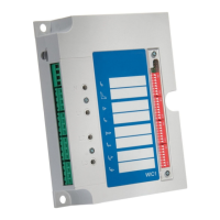
CAUTION!
For a WIC1‑4, it is also necessary that the congured operating mode matches the
connected hardware!
(For example, it is not permissible to connect a ag indicator and set the operating mode
to “Syst. O.K. & Ext.Suppl.”. See also the related Self-Supervision warnings SW 3, SW 4.)
Moreover, the electrical energy that an output relay drains with operating mode “Syst.
O.K. & Ext.Suppl.” requires that the WIC1‑4 is supplied by an external auxiliary voltage.
7.1.4.3 Self-Supervision Contact for the WIC1‑4
An externally supplied WIC1‑4 allows for connecting an output relay that operates
as a “Healthy” / self-supervision contact. (See ╚═▷ “3.7.1 Self-Supervision Contact for
the WIC1‑4”.)
7.1.4.4 WIC1 Settings
The protection parameters must be carefully set, see the respective chapters in this
document. For later reference, the setting values can be written directly on the sticker that
is axed on the relay.
7.1.5
Functional Test
There are two methods to carry out the tests: Primary test and secondary test.
When the primary test method is used, the test current is impressed via the
primary winding.
When the secondary test method is used, the test current is impressed via the C–D test
winding, see also ╚═▷ “7.1.4.1 Test Windings, Test Sockets”.
193WIC1WIC1-1.0-EN-MAN
7 Commissioning
7.1.4.3 Self-Supervision Contact for the WIC1‑4

 Loading...