3.7.3
Impulse Signal for the Flag Indicator
A ag indicator can be connected to terminals FI+/FI− (WIC1‑4: Out+/Out−) of the terminal
block X4, e. g. for a power-safe signaling of a trip.
The energy is provided by a capacitor store integrated in the WIC1 protection relay. The
length of the trip impulse is approx. 50 ms, the pause between the individual pulses depends
on the impedance of the ag indicator and the current level. Pulsing is continued until the
assigned signal drops o.
Technical Data for the Setting Pulse
• Energy: E ≈ 0.01 Ws•
• Voltage: V ≈ 24 VDC•
CAUTION!
It is not allowed to connect any continuous / active voltage to the setting contact or to
the reset contact of the ag indicator!
Any continuous voltage can destroy the coil that is built into the ag indicator.
For a WIC1‑4, in particular, it is not permissible to connect a ag indicator and set the
operating mode of the output to “output relay” (see ╚═▷ “Relay Output (WIC1‑4)”).
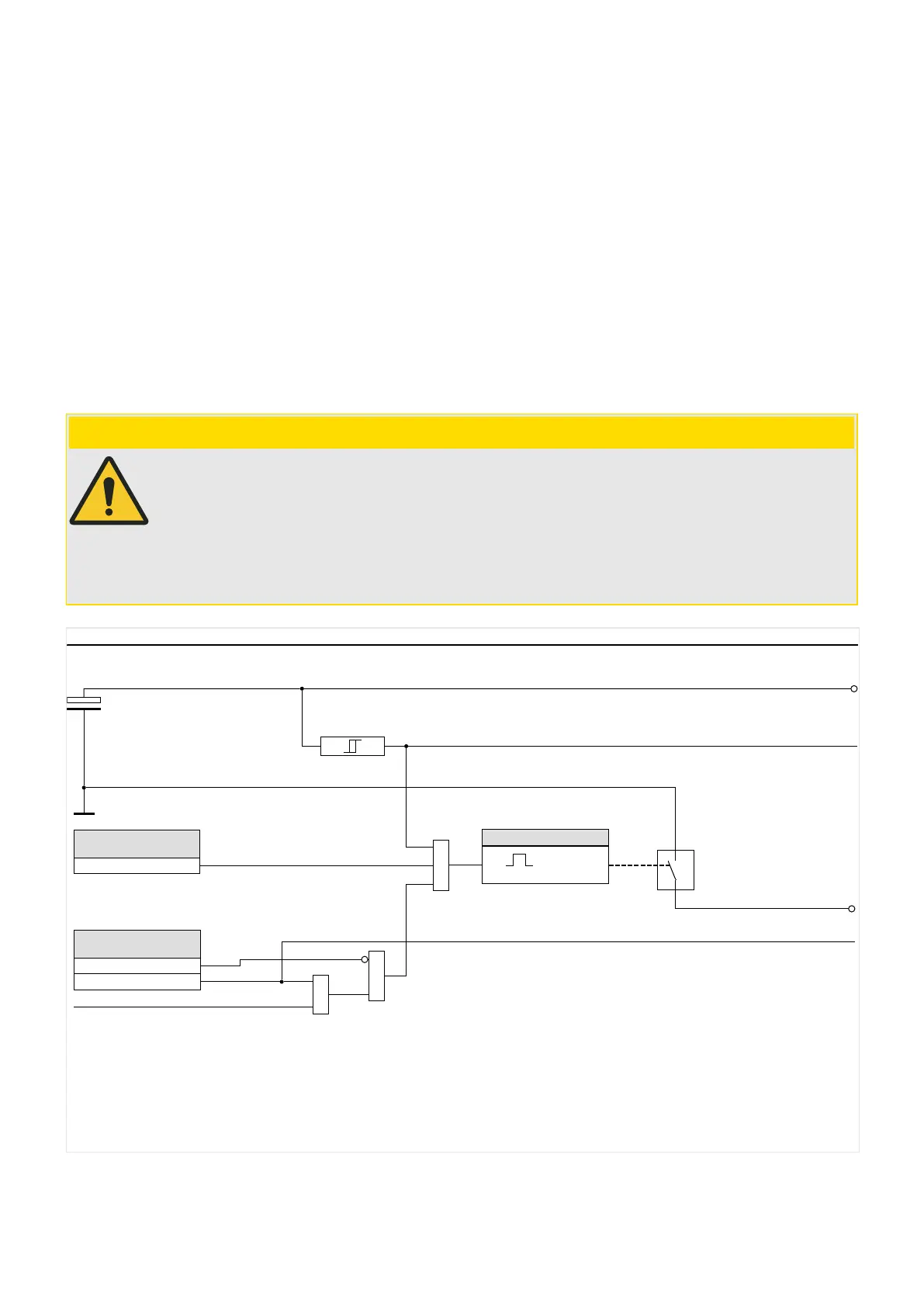
FI assign.
wiProtGeneral_Y08
Output “FI−”
&
Energy Storage FI
Output “FI+”
Device has enough energy for FI pulse
50 ms
1
t
Prot .
FI assign.
no assignment
1..n, Assignment List
Prot . FI assign.-I
Prot . FI Inverting
=1
&
Prot .
Out. Mode *
Impulse Output
(Flag Indicator)
Fig. 33:
Signal assignment for ag indicator (output “FI+/−”).
* Setting »Prot . Out. Mode« can be changed only for a WIC1‑4 with external power supply.
For all other WIC1 variants it is hidden and xed to “Impulse Output”. See also ╚═▷ “Relay
Output (WIC1‑4)”.
92 WIC1 WIC1-1.0-EN-MAN
3 Hardware
3.7.3 Impulse Signal for the Flag Indicator

 Loading...

