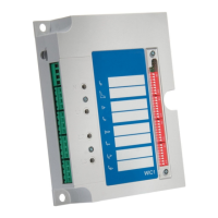
Ground Current Input:
Overcurrent Proof: 50 x In / 1 s
Power Consumption: S ≤ 0.1 VA
9.1.6
Power Supply
Supply via CTs
• Minimum supply current, 1 Phase: 0.35 In
,min
•
• Minimum supply current, 3 Phases: 0.25 In
,min
•
Auxiliary Power Supply (WIC1‑4)
Aux. Voltage:
• 18 … 300 VDC•
• 40 … 250 VAC•
Buer Time in Case of Supply Failure: ≥ 50 ms at minimal aux. voltage
The device will shut down if the buer
time is expired.
Note: communication can be interrupted.
The auxiliary voltage supply must be protected by an external fuse of:
•
2.5 A time-lag miniature fuse 5 x 20 mm (approx. 1/5 x 0.8 in.) according to IEC
•
60127
• 3.5 A time-lag miniature fuse 6.3 x 32 mm (approx. 1/4 x 1 ¼ in.) according to UL•
248-14
9.1.7
LEDs
LED type: 1 green LED, 2 red LEDs
9.1.8 Outputs
CAUTION!
It is not allowed to connect any active voltage to the trip coil output or to the output
(ag
indicator / relay output).
The two outputs may be connected at the same time to test equipment (e. g. to binary
inputs of an Omicron
©
device) only if these two binary inputs do not share a common
potential. Otherwise this external potential bridge, together with device-internal circuits,
can produce incorrect test results.
207WIC1WIC1-1.0-EN-MAN
9 Technical Data
9.1.6 Power Supply

 Loading...