3 Hardware
3.1
Overview of Elements and Connectors
NOTICE!
The controls and connectors, that the WIC1 is tted with, depends on the Order Form of
the WIC1.
Front Side
ON DIP
1 2 3 4 5 6 7 8
ON DIP
1 2 3 4 5 6 7 8
ON DIP
1 2 3 4 5 6 7 8
ON DIP
1 2 3 4 5 6 7 8
ON DIP
1 2 3 4 5 6 7 8
ON DIP
1 2 3 4 5 6 7 8
C
4
B
3
A
2
9
1
0
8
F
7
E
6
D
5
C
4
B
3
A
2
9
1
0
8
F
7
E
6
D
5
C
4
B
3
A
2
9
1
0
8
F
7
E
6
D
5
C
4
B
3
A
2
9
1
0
8
F
7
E
6
D
5
C
4
B
3
A
2
9
1
0
8
F
7
E
6
D
5
C
4
B
3
A
2
9
1
0
8
F
7
E
6
D
5
C
4
B
3
A
2
9
1
0
8
F
7
E
6
D
5
C
4
B
3
A
2
9
1
0
8
F
7
E
6
D
5
C
4
B
3
A
2
9
1
0
8
F
7
E
6
D
5
C
4
B
3
A
2
9
1
0
8
F
7
E
6
D
5
C
4
B
3
A
2
9
1
0
8
F
7
E
6
D
5
C
4
B
3
A
2
9
1
0
8
F
7
E
6
D
5
WIC1-1, WIC1-4 WIC1-2 WIC1-3
LEDs
WIC1_Z08
Switches: DIP
Switches: HEX
Ready Error Pic k up
Trip
IG
IL1
IL2
IL3
N
1
2
X4X5
X6
1
2
3
4
5
6
7
8
FI+
FI−
T C+
T C−
DiggiMEC
1
3
4
5
6
2
HF
GND
T-
N
P
T+
RS485
1
1
1
C
D
1S1
C
D
1S2
2S1
2S2
1S1
1S2
C
D
1S1
C
D
1S2
2S1
2S2
1S1
1S2
C
D
1S1
C
D
1S2
2S1
2S2
1S1
1S2
X3
IL3
X2
IL2
X1
IL1
X0
IG
I
n
I
I>
t
l>
I>>
t
I>>
IG>
t
IG>
IG
IH2
%
l
peak>
IH2
max
PE X7
Ethe r net
Test Sockets
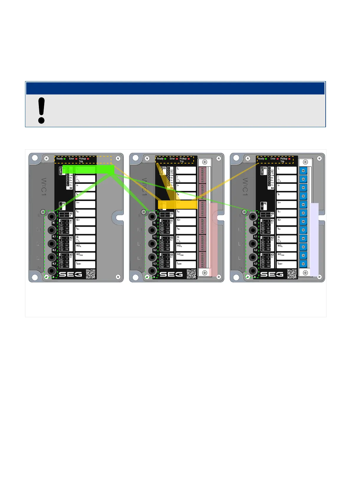
Fig. 5: Main elements at the front side of the WIC1.
The front side of the WIC1 is equipped with LEDs (for operation and alarm signals, see ╚═▷
“3.8.1 LEDs”) and several test sockets, see ╚═▷ “7.1.4.1 Test Windings, Test Sockets”.
53WIC1WIC1-1.0-EN-MAN
3 Hardware
3.1 Overview of Elements and Connectors
 Loading...


