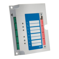
Reaction Time:
• < 20 ms
(*)
•
Tripping time of the External Protection in case
of a cold restart:
≤ 0.5 s
(*)
The reaction times have been measured with a WIC1 that is ready to trip (i. e. green Ready
LED is lit). They are the time-span for the External Protection from activation of the trigger
signal until activation of the “TC+/−” impulse output.
9.1.10
Digital Inputs (WIC1‑4)
A device of type WIC1‑4 can feature 2 Digital Inputs (depending on the order option). For
variants WIC1-4xxxxF there is a xed assignment to “External Trip” and “External Reset”,
respectively. For variants WIC1-4xxxxC, this is a default assignment that can be re-dened.
The Digital Inputs are not potential-free, i. e. they are not isolated from the housing and
from the internal electronics. Moreover, the two Digital Inputs of the WIC14 are grouped, i. e.
share a common electrical potential.
The input voltage range can be selected by software parametrization.
Voltage Range Nominal Voltage Digital “Low” / “0”
below 0.4 Vn
(20% below
switching
threshold)
Switching
Threshold at 0.6 Vn
(± 20%)
Digital “High” / “1”
above 0.8Vn
(20% above
switching
threshold)
24 VDC 24.0 VDC 9.6 VDC 14.4 VDC 19.2 VDC
48 VDC … 60 VDC 52.0 VDC 20.8 VDC 31.2 VDC 41.6 VDC
110 VDC / 110 VAC 110.0 VDC / 110.0
VAC
44.0 VDC / 44.0 VAC 66.0 VDC / 66.0 VAC 88.0 VDC / 88.0 VAC
230 VDC / 230 VAC 220.0 VDC / 220.0
VAC
88.0 VDC / 88.0 VAC 132.0 VDC / 132.0
VAC
176.0 VDC / 176.0
VAC
Terminals: Screw-type terminal
Max. Input Voltage: 300 VDC / 259 VAC
Input Current: < 1 mA
Reaction Time:
•
for DC: < 10 ms
(*)
•
• for AC: < 20 ms
(*)
•
(*)
The reaction times have been measured with a WIC1 that is ready to trip (i. e. green Ready
LED is lit). They are the time-span for the External Protection from activation of the trigger
signal until activation of the “TC+/−” impulse output.
9.1.11 Smart view Connections
The WIC1 can communicate with the operating software Smart view via a USB connection
to a DiggiMEC. (See also ╚═▷ Fig. in ╚═▷ “2.7 Settings – Operation”.)
210 WIC1 WIC1-1.0-EN-MAN
9 Technical Data
9.1.10 Digital Inputs (WIC1‑4)

 Loading...