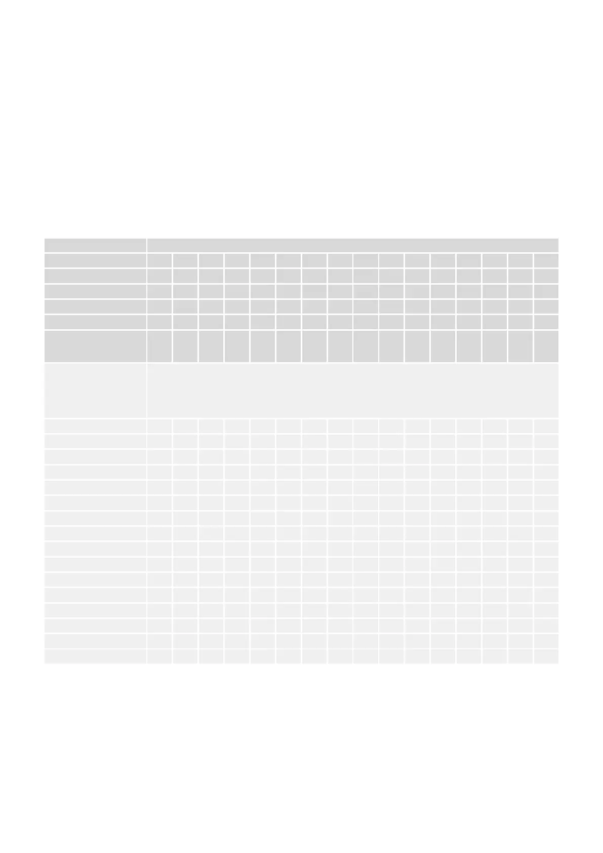
7.1.5.2 Pickup Thresholds for the Phase Overcurrent Stage I>
The nominal current In is set via the switches DIP 1‑1...1‑4 or HEX 1 (independent of the CT
type in units of the lower current limit In
,min
).
Via the switches DIP 2‑1...2‑4 or HEX 3, the pickup threshold I> is set, but this is in units of
In. (See also ╚═▷ “11.1 Appendix – Settings via DIP / HEX Switches”.)
Therefore the pickup threshold I> in Ampere depends on both DIP 1‑1...1‑4 / HEX 1 and
on DIP 2‑1...2‑4 / HEX 3, and consequently there is an analogous dependency for the test
current (in Ampere) that needs to be fed into the C–D winding. The following table shows this
test current (in Ampere):
I> Setting of the I> threshold
DIP 2-1 OFF ON OFF ON OFF ON OFF ON OFF ON OFF ON OFF ON OFF ON
DIP 2-2 OFF OFF ON ON OFF OFF ON ON OFF OFF ON ON OFF OFF ON ON
DIP 2-3 OFF OFF OFF OFF ON ON ON ON OFF OFF OFF OFF ON ON ON ON
DIP 2-4 OFF OFF OFF OFF OFF OFF OFF OFF ON ON ON ON ON ON ON ON
HEX switch 3 0 1 2 3 4 5 6 7 8 9 A B C D E F *
Resulting setting I>
[In] →
0.90 0.95 1.00 1.05 1.10 1.15 1.20 1.30 1.40 1.50 1.60 1.80 2.00 2.25 2.50 — *
Setting for the nominal
current In
[In
,min
]
↓
Test current via C–D winding
[A]
↓
Hex 1 = „0“ (In = 1.0) 0.288 0.304 0.320 0.336 0.352 0.368 0.384 0.416 0.448 0.480 0.512 0.576 0.640 0.720 0.800 — *
Hex 1 = „1“ (In = 1.125) 0.324 0.342 0.360 0.378 0.396 0.414 0.432 0.468 0.504 0.540 0.576 0.648 0.720 0.810 0.900 — *
Hex 1 = „2“ (In = 1.25) 0.360 0.380 0.400 0.420 0.440 0.460 0.480 0.520 0.560 0.600 0.640 0.720 0.800 0.900 1.000 — *
Hex 1 = „3“ (In = 1.375) 0.396 0.418 0.440 0.462 0.484 0.506 0.528 0.572 0.616 0.660 0.704 0.792 0.880 0.990 1.100 — *
Hex 1 = „4“ (In = 1.5) 0.432 0.456 0.480 0.504 0.528 0.552 0.576 0.624 0.672 0.720 0.768 0.864 0.960 1.080 1.200 — *
Hex 1 = „5“ (In = 1.625) 0.468 0.494 0.520 0.546 0.572 0.598 0.624 0.676 0.728 0.780 0.832 0.936 1.040 1.170 1.300 — *
Hex 1 = „6“ (In = 1.75) 0.504 0.532 0.560 0.588 0.616 0.644 0.672 0.728 0.784 0.840 0.896 1.008 1.120 1.260 1.400 — *
Hex 1 = „7“ (In = 1.875) 0.540 0.570 0.600 0.630 0.660 0.690 0.720 0.780 0.840 0.900 0.960 1.080 1.200 1.350 1.500 — *
Hex 1 = „8“ (In = 2.0) 0.576 0.608 0.640 0.672 0.704 0.736 0.768 0.832 0.896 0.960 1.024 1.152 1.280 1.440 1.600 — *
Hex 1 = „9“ (In = 2.125) 0.612 0.646 0.680 0.714 0.748 0.782 0.816 0.884 0.952 1.020 1.088 1.224 1.360 1.530 1.700 — *
Hex 1 = „A“ (In = 2.25) 0.648 0.684 0.720 0.756 0.792 0.828 0.864 0.936 1.008 1.080 1.152 1.296 1.440 1.620 1.800 — *
Hex 1 = „B“ (In = 2.5) 0.720 0.760 0.800 0.840 0.880 0.920 0.960 1.040 1.120 1.200 1.280 1.440 1.600 1.800 2.000 — *
Hex 1 = „C“ (In = 2.75) 0.792 0.836 0.880 0.924 0.968 1.012 1.056 1.144 1.232 1.320 1.408 1.584 1.760 1.980 2.200 — *
Hex 1 = „D“ (In = 3.0) 0.864 0.912 0.960 1.008 1.056 1.104 1.152 1.248 1.344 1.440 1.536 1.728 1.920 2.160 2.400 — *
Hex 1 = „E“ (In = 3.25) 0.936 0.988 1.040 1.092 1.144 1.196 1.248 1.352 1.456 1.560 1.664 1.872 2.080 2.340 2.600 — *
Hex 1 = „F“ (In = 3.5) 1.008 1.064 1.120 1.176 1.232 1.288 1.344 1.456 1.568 1.680 1.792 2.016 2.240 2.520 2.800 — *
— * This DIP / HEX setting deactivates the protection stage.
195WIC1WIC1-1.0-EN-MAN
7 Commissioning
7.1.5.2 Pickup Thresholds for the Phase Overcurrent Stage I>
 Loading...


