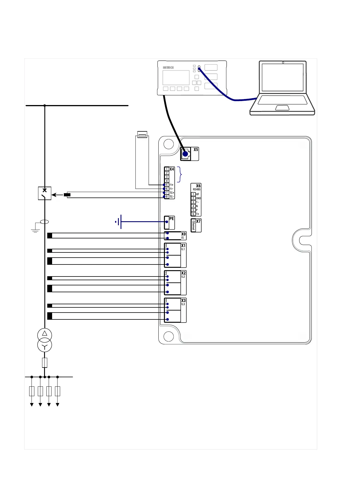
2.1 Basic Wiring Concept
IG
WIC1_Z0F
Ready Error Pic k up
Trip
IG
IL1
IL2
IL3
N
1
2
X4X5
X6
1
2
3
4
5
6
7
8
FI+
FI−
T C+
T C−
DiggiMEC
1
3
4
5
6
2
HF
GND
T-
N
P
T+
RS485
1
1
1
C
D
1S1
C
D
1S2
2S1
2S2
1S1
1S2
C
D
1S1
C
D
1S2
2S1
2S2
1S1
1S2
C
D
1S1
C
D
1S2
2S1
2S2
1S1
1S2
X3
IL3
X2
IL2
X1
IL1
X0
IG
I
n
I
I>
t
l>
I>>
t
I>>
IG>
t
IG>
IG
IH2
%
l
peak>
IH2
max
PE X7
Ethe r net
WIC1
PE
C/D
1S1
1S2
C/D
1S1
1S2
C/D
1S1
1S2
trip coil
SCADA
−+
FI
DiggiMEC
Network Cable
USB Cable
X4–1...4:
Digital Inputs And/or
Power Supply
IL2
Test IL2 *
IL1
Test IL1 *
IL3
Test IL3 *
−
+
Current source, three phases
plus wiring for ground current measurement
Fig. 2: Basic wiring concept.
(*) The test windings “C–D” are only needed for the secondary tests during commissioning,
see ╚═▷ “7.1.4 Checks During Commissioning”.
19WIC1WIC1-1.0-EN-MAN
2 WIC1 – Introduction and General Information
2.1 Basic Wiring Concept
 Loading...


