WI1SZ5_Z01
violet
FI+
FI−
Reset
WIC1
brown
External Signals
red
yellow
blue
[1.]
black
green
white
[2.] [3.] [4.] [5.]
[5.]
[6.]
[7.]
[8.] [9.] [7.]
[6.]
Reset
orange
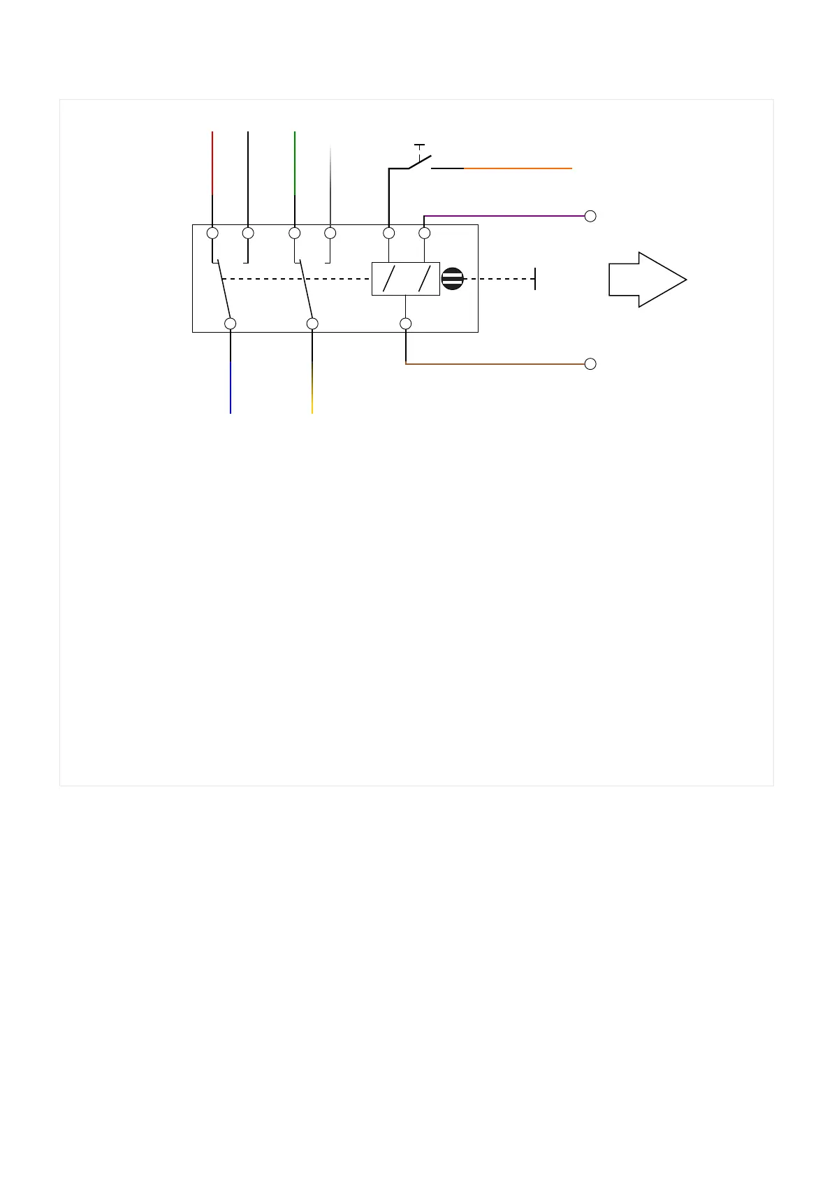
Fig. 32: Connection diagram for the WI1SZ5 ag indicator.
[1.] red cable, ⌀ = 0.5mm²: NC contact number 1
[2.]
black cable, ⌀ = 0.5mm²: NO contact number 1
[3.] green cable, ⌀ = 0.5mm²: NC contact number 2
[4.] white cable, ⌀ = 0.5mm²: NO contact number 2
[5.] orange cable, ⌀ = 0.25mm²: reset contact (+)
[6.]
violet cable, ⌀ = 0.25mm²: set contact (+)
[7.] brown cable, ⌀ = 0.25mm²: ground contact (−)
[8.] yellow cable, ⌀ = 0.5mm²: Common contact number 2
[9.] blue cable, ⌀ = 0.5mm²: Common contact number 1
91WIC1WIC1-1.0-EN-MAN
3 Hardware
3.7.2 Connecting a Flag Indicator to the WIC1
 Loading...


