R
wic1
Impedance of the adapter CT plus WIC1
ALF Accuracy limit factor
E
k
Rated knee point e.m.f.
V
s
Secondary terminal voltage of the standard CT
When dimensioning the standard current transformers, the following conditions hold for the
setting »CT . In,relative« = 1.0:
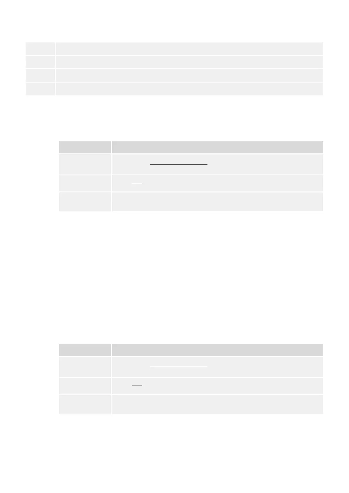
Minimum Requirement: Make sure that an Overcurrent Causes a Trip
CT class Minimum Requirement
P, PR
ALF ≥ 20 ⋅
R
ct
+ R
wiring
+ R
wic1
R
ct
+ R
b
PX, PXR
E
k
≥
20
1.2
⋅ I
sr
⋅
⎛
⎝
R
ct
+ R
wiring
+ R
wic1
⎞
⎠
IEEE / ANSI C-
class
V
s
≥ 20 ⋅ I
sr
⋅
⎛
⎝
R
ct
+ R
wiring
+ R
wic1
⎞
⎠
• R
wic1
for normal connection, as shown in ╚═▷ Fig. 20: R
wic1
= 0.2 Ω•
• R
wic1
for Holmgreen connection, as shown in ╚═▷ Fig. 21: R
wic1
= 0.3 Ω•
The current limit of the adapter CTs is specied as 100 In for 1 second. (See the Technical
Data.) The maximum short-circuit current and the protection settings (including time
delays) must be below this limit:
I
psc,max
≤ 100 I
pr
= 100 In
If this is not feasible and the maximum short-circuit current is too high – I
psc,max
> 100 I
pr
–
the size of the standard CTs can be limited so that the current ow through the adapter CTs
is limited to I ≤ 100 I
sr
. Only in this case must the maximum requirement – as described
below – be considered as well.
Maximum Requirement: The Adapter CT Must Not be Thermally Overloaded
CT class Maximum Requirement
P, PR
ALF ≤ 80 ⋅
R
ct
+ R
wiring
+ R
wic1
R
ct
+ R
b
PX, PXR
E
k
≤
80
1.2
⋅ I
sr
⋅
⎛
⎝
R
ct
+ R
wiring
+ R
wic1
⎞
⎠
IEEE / ANSI C-
class
V
s
≤ 80 ⋅ I
sr
⋅
⎛
⎝
R
ct
+ R
wiring
+ R
wic1
⎞
⎠
• R
wic1
for normal connection, as shown in ╚═▷ Fig. 20: R
wic1
= 0.1 Ω•
• R
wic1
for Holmgreen connection, as shown in ╚═▷ Fig. 21: R
wic1
= 0.1 Ω•
75WIC1WIC1-1.0-EN-MAN
3 Hardware
3.3.3.1 Requirements for 1 A Standard CTs being Used with Adapter CTs
 Loading...


