• For the latching of DiggiMEC ag indicators / output relays, [Device Para / DiggiMEC /•
FI / BO] »BO x latching« = “Latching w. Auto-Reset”
(See also ╚═▷ “3.9.3.1 Latching”.)
• For the latching of DiggiMEC LEDs, [Device Para / DiggiMEC /•
LEDs] »LED x latching« = “Latching w. Auto-Reset”
See also ╚═▷ “3.8.1.3 Latching of the DiggiMEC LEDs”.)
•
The behavior of the automatic reset itself is set at [Device Para / Reset] »Def. Autom.
•
Reset«
Note that the automatic reset is closely related to the (General) Pickup signal »Prot .
Pickup«, and therefore we recommend to always use it only with states that indicate any
protection pickup or trip.
If, however, an automatic reset is assigned to a state that is not related to any pickup or trip,
the resulting reset behavior might be surprising (although it is exactly what one needs for
real-life applications): Every protection pickup also issues the signal »Prot . Pickup«, see ╚═▷
“4.1 »Prot« – General Protection Module”, and this signal starts the automatic reset. This
means, of course, that all states (that are set to latching with automatic reset) get reset,
and moreover, states that are assigned to this new protection pickup, get set (again). If the
automatic reset is congured with a timer stage, for instance »Def. Autom. Reset« = “New
Pickup or After 1 h”, then the signal »Prot . Pickup« starts this timer. And after the timer has
elapsed, i. e. after one hour, all states (that are set to latching with automatic reset) get
reset (again). So, unless there will be another protection pickup within this hour the result is
that after one hour all states (that are set to latching with automatic reset) are reset.
But now let us consider a state, that is set to latching with automatic reset, but is assigned
to some signal that is in no way related to any protection pickup or trip. This state would
not get reset after one hour, because the timer stage always only starts with a »Prot .
Pickup« signal. This means that only when a protection pickup should occur, will this state
be reset (and once again after one hour).
Notication of a Problem via LED
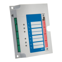
The second, red LED of the WIC1 can notify you of a device-internal problem by ashing red,
see ╚═▷ “The »System« LED(s) – “Ready”, “Error””. Contrast to a constant red illumination
the ashing means that the overall protection functionality is fully active and not aected
by the problem. Therefore it is possible to reset (“acknowledge”) the ashing LED.
This is done with the following Direct Control:
•
[Operation / Reset] »Reset ERROR LED«
•
Although the protection functionality is essentially active it is apparently advisable to check
for the problem that has caused the ashing LED, and for potential solutions. Check the
entries in the Fault Recorder (╚═▷ “5 Fault Recorder”) and the list of potential problems in
╚═▷ “10 Troubleshooting”.
50 WIC1 WIC1-1.0-EN-MAN
2 WIC1 – Introduction and General Information
2.11 Reset

 Loading...