24
www.seuservice.com
Instructions for attaching the R (right) side are included in this manual. The procedure for at-
taching the L (left) side is the same.
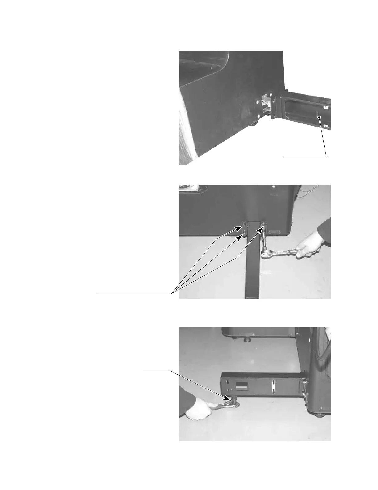
Attach the foot base to the U-
shaped bracket sticking out from
the side of the controller cabinet by
inserting it from the side.
PHOTO 6. 3 d
FOOT BASE R (L)
Secure the foot base with 4 hex-
agonal bolts.
PHOTO 6. 3 e
Set foot base adjuster.
Set adjuster.
PHOTO 6. 3 f
HEXAGONAL BOLT (4), black
M8×35, w/spring washer,
at washer used