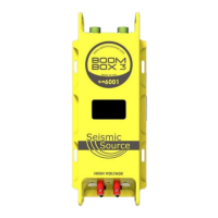
10. Boom Box 3 Weight Drop
The Boom Box 3 Unit can be used in weight drop mode like the RTM3 Unit. The connections
with the Boom Box 3 have to be done through the 37 DSUB connector.
10.1 Boom Box 3 in RTM Mode Systems
10.2.1 Basic Connections
The Basic RTM mode features the following:
Display – shows basic operation and setup of the system. The display can be used to show
status of the radio telemetry plus GPS and hardware interface.
10 pin Female connector – Ethernet Port. Connect the 10 pin to RJ45 cable to this connector
and plug the RJ45 into any windows computer. SourceLink software can be used to setup and
display the operational parameters.
10 pin Male connector – Power/ Radio/GPS. This connector is used to connect the DC power
(10 to 30 volts DC input), the Radio Interface (5 pin connector), and the GPS connector (4 pin
connector).
37 pin connector – This connector is used primarily to connect the Boom Box 3 encoder to the
recording system. This connector is also used to connect the Boom Box 3 in RTM decoder
mode to the hammer switch.
10.2.2 Autonomous Configuration
10.2.2.1 BOOM BOX 3 in RTM mode Autonomous Equipment
The Basic BOOM BOX 3 (in RTM decoder mode) Autonomous system includes the
following:
• BOOM BOX 3 unit
• RTM 3 Decoder Cable set
• GPS module
10.2.3 Managed Configuration
Two BOOM BOX 3 systems are required. One BOOM BOX 3 system must be set up as an RTM
Encoder and one BOOM BOX 3 must be setup as a RTM Decoder

 Loading...