39 BOOM BOX 3 Dynamite Controller
10.6.2 Source-Driven Operation
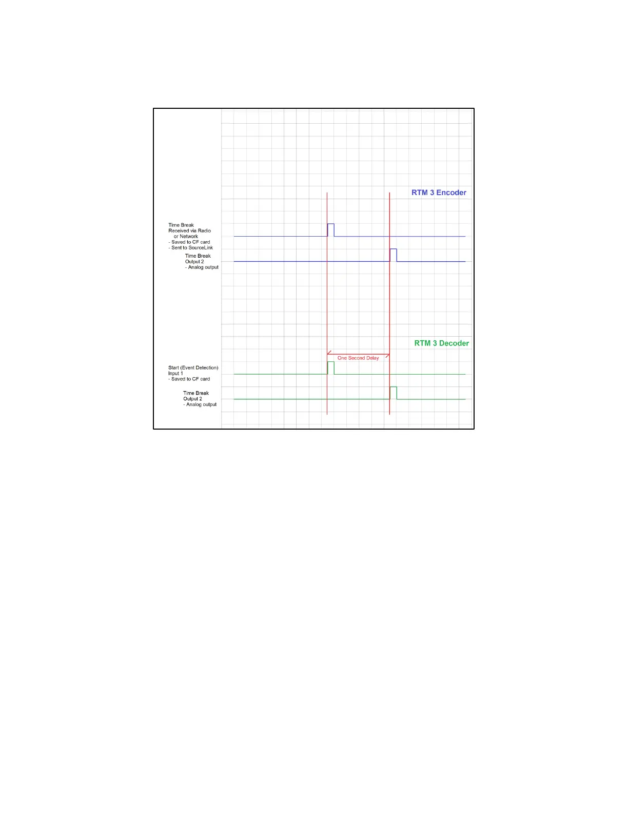
10.6.2.1 Source-Driven Timing
10.6.2.2 Source-Drive Operation
1) The Decoder waits for a switch closure, or a voltage level change, on the “START”
hardware logic line. This line is normally connected to a hammer switch, mounted on the
sledgehammer handle or the baseplate of the AWG/EWG. The exact time of the Hit is
calculated.
2) The Decoder saves the Hit time, the last GPS position received before the Hit occurred,
and three channels of analog input data starting at the hit time, plus the PFS data, to the
internal CF memory card.
3) The Decoder sends a message via radio to the BOOM BOX 3 (in RTM encoder mode)
Encoder. This message includes the Hit time, GPS position, and other Quality Control
information.
4) The Encoder outputs the digital Hit Message to the Ethernet port.
5) Both the Encoder and Decoder output a Time Break signal on the “Time Break” hardware
lines, exactly 1 second after the Event time determined by the Decoder.