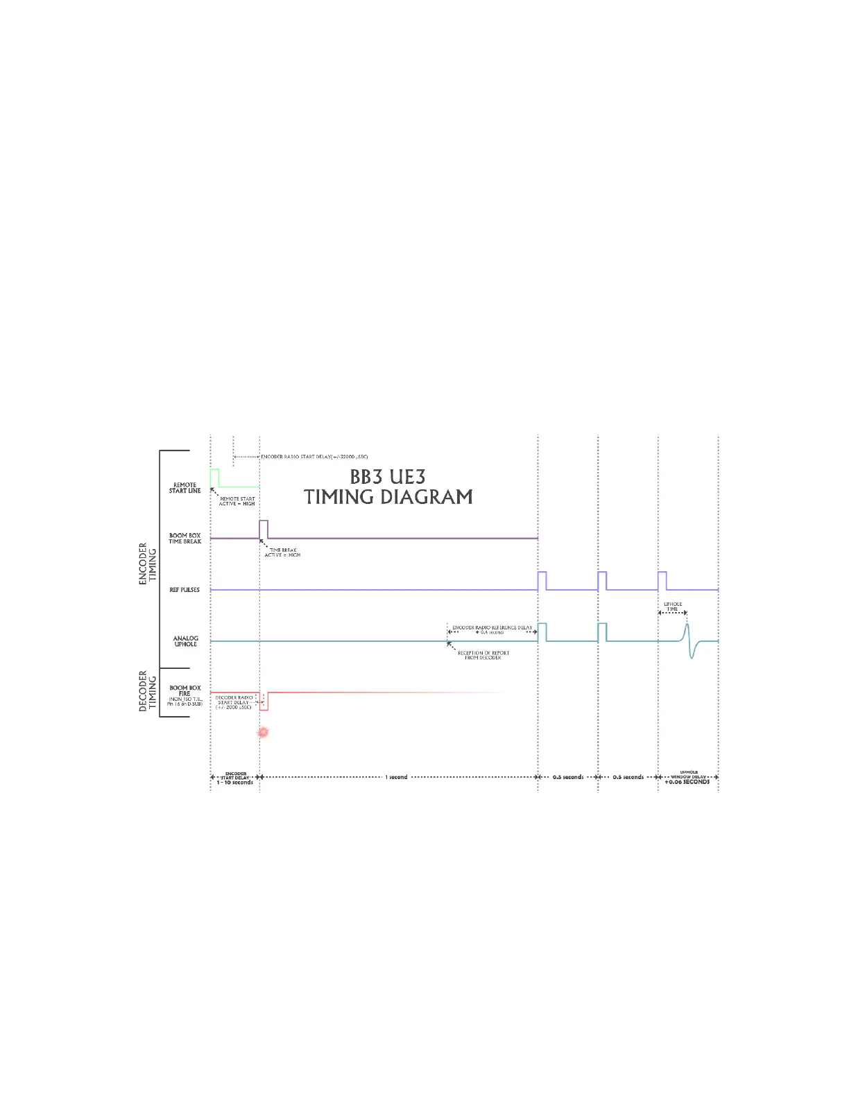
• The Encoder outputs the following timing pulses. These pulses are based on when the
Shot Status Message is received.
o Data reception pulse – Pulse that is generated if Shot Status Message is received.
This pulse should be at 1 second plus one-way radio delay.
o Confirmation Time Break – This pulse will be generated if current to CAP
exceeded threshold. This pulse is generated 0.5 seconds after Data Reception
Pulse.
o Uphole Data – The analog uphole data is reproduced exactly 1 second after the
Data Reception Pulse.
o Source Control F3 program or SourceLink v.22+ program, Encoder Parameters,
Similarity Delay entry is used to align the Data reception pulse with the one second
Reference pulse.
• The Source Control F3 program or SourceLink v.22+ program can be used to view the
following
o The Shot Status message from the Decoder
o GPS information before or after shot
o View Resistance measurements before or after shot
9.1.2 Start Code
Three parameters must match for a valid start code to be recognized.
• Start Code – (0-3) – All Boom Box units must be set to the same number
• Crew number – (0-250) – All Boom Box units must be set to the same number.
• Units – Decoder unit ID number must be included in the list of units of the selected
sequence within Source Control F3 program.