10.6 BOOM BOX 3 in RTM decoder mode Operation
10.6.1Autonomous Operation
10.6.1.1Autonomous Timing
10.6.1.2 Autonomous Operation
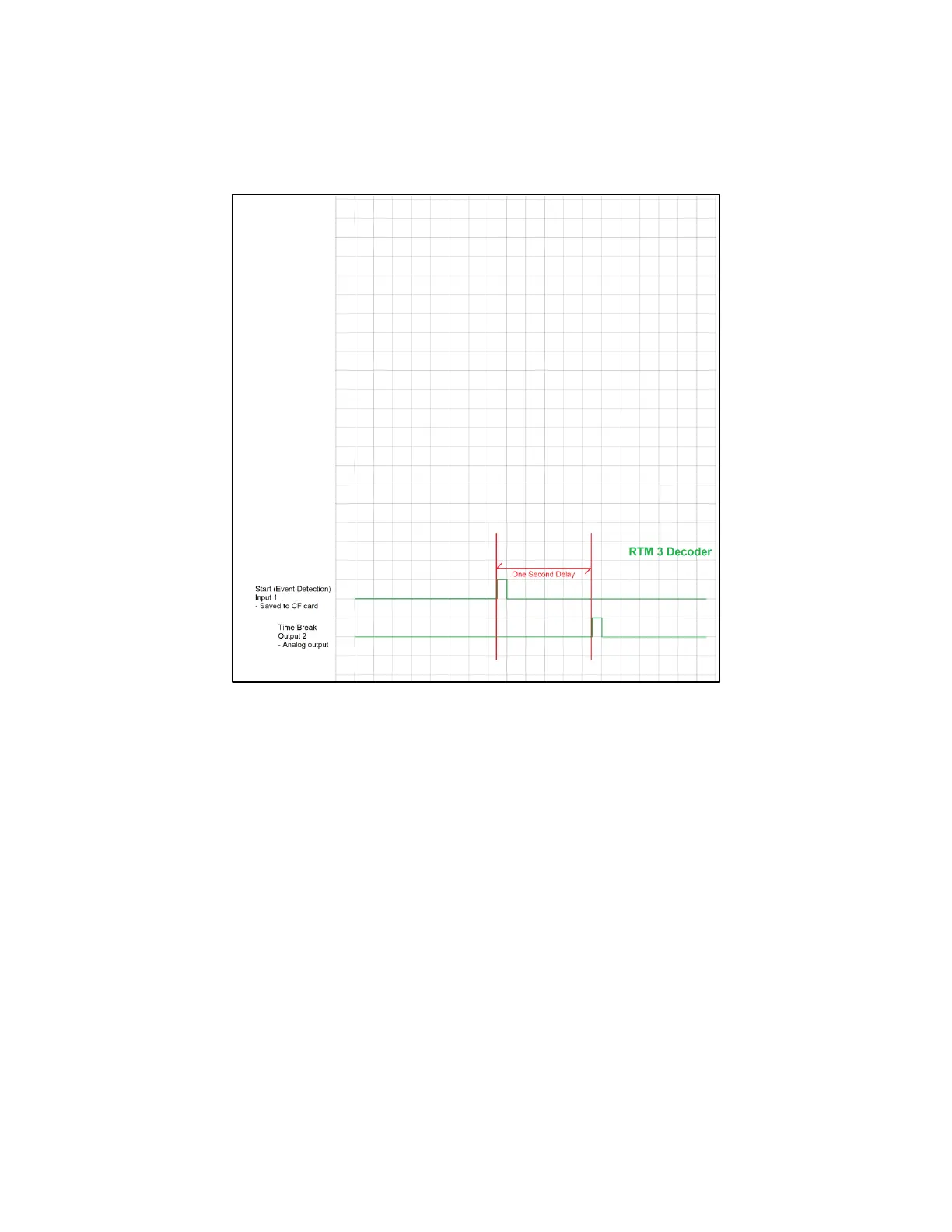
1) The Decoder waits for a switch closure, or a voltage level change, on the “START”
hardware logic line. This line is normally connected to a “hammer switch”, mounted on
the sledgehammer handle or the baseplate of the AWG/EWG. The exact time of the Hit is
calculated.
2) The Decoder saves the Hit time, the last GPS position received before the Hit occurred,
and three channels of analog input data starting at the hit time, plus the PFS data, to the
internal CF memory card.
3) This data is later downloaded to SEG-Y files from the BOOM BOX 3 internal memory.
4) Exactly one second after the hit event is detected, a pulse is sent on the Time Break line.