10.6.3 Decoder-Driven Operation
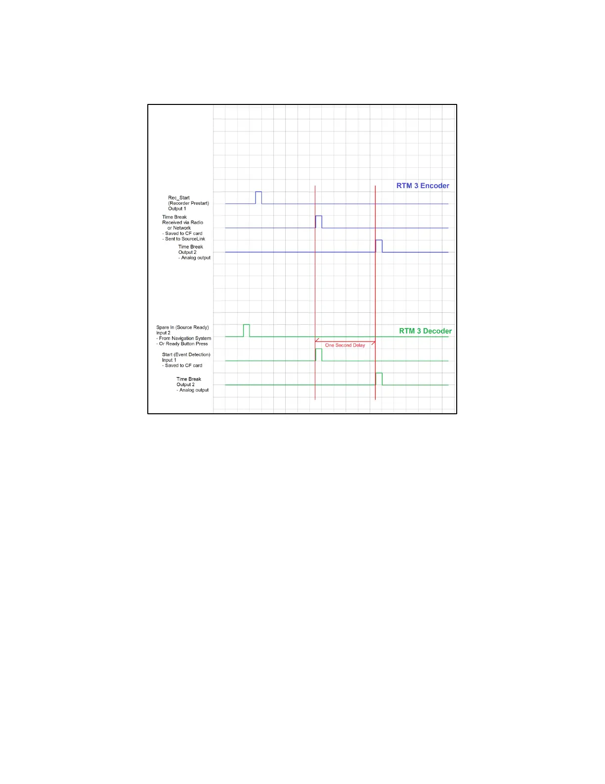
10.6.3.1 Decoder-Driven Timing
10.6.3.2 Decoder-Driven Operation
1) BOOM BOX 3 (in RTM decoder mode) Decoder Receives a “Ready” command. This is
initiated by a hardware command, e.g., a voltage change from a navigation system or a
Ready Button switch closure, on the “Spare In” line.
2) The Decoder sends a message via radio to the BOOM BOX 3 (in RTM encoder mode)
Encoder. This message includes the Hit time, GPS position, and other Quality Control
information.
3) When the Ready message is received by the BOOM BOX 3 (in RTM encoder mode)
Encoder, the Encoder outputs a logic level on the “RecStart” logic line. It also output an
Ethernet Ready Message.
4) After the Decoder unit has received the hardware start command, it waits for a pre-
determined local start delay and outputs fire signal on the “RecStart” line.
5) The Decoder then waits for a hardware event on the “START” hardware logic line. The
exact time of this event is calculated from the GPS.
6) The Decoder saves the Hit time, the last GPS position received before the Hit occurred,
and three channels of analog input data starting at the hit time, plus the PFS data, to the
internal CF memory card.
7) The Decoder sends a Hit message via radio to the Encoder. This message includes the Hit
time, GPS position, and other Quality Control information.
8) The Encoder outputs the digital Hit Message in the Ethernet port.
9) Both the Encoder and Decoder output a Time Break signal on the “Time Break” hardware
lines, exactly 1 second after the Event time determined by the Decoder.