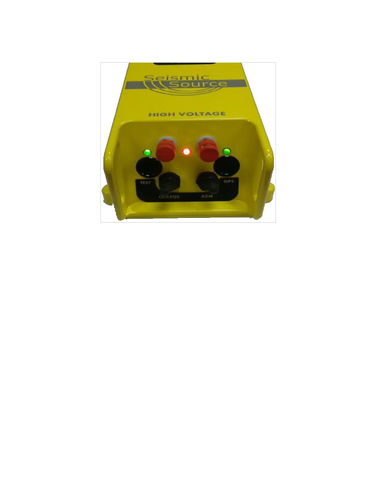
3. Front Panel Description
Boom Box 3 Front Panel contains:
• 2 High Voltage terminals – connect to CAP wire for firing dynamite.
• Red Power/Status LED
o Decoder Mode – flashes ON in short bursts.
o Decoder Mode Charging – Flashes Fast when charged
• ARM toggle switch
o Power up Boom Box 3 – single press powers the box “on”
o Arm the dynamite CAP line – must hold switch to “ARM” high voltage terminals
o The ARM switch in the normal position shorts the high-voltage line
• Charge toggle switch
o Press Charge to charge the High Voltage Capacitor
• Test Push Button
o Press Test button to test the Geophone
o Press Test and ARM button to test the dynamite CAP
o Test LED shows result of test
• GPS Push Button
o Press GPS button to store the GPS position for the next shot
o To reacquire GPS for the same shot, hold Charge button and then press GPS button
o GPS LED shows status of GPS position