13 BOOM BOX 3 Dynamite Controller
3.1.1 Display
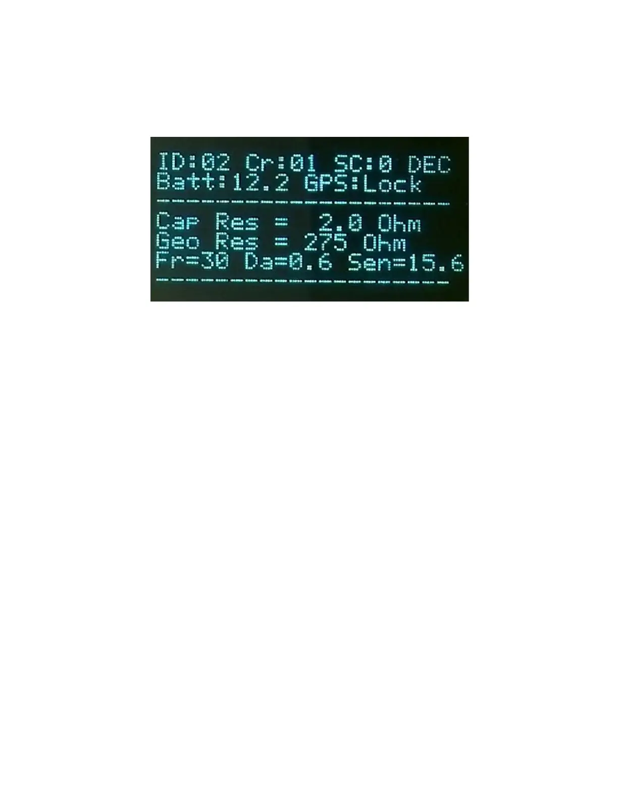
The Boom Box 3 has a graphical display. The display is used to show the setup of the box at
power on, the CAP and Geophone resistance, the ready message, the uphole information, and the
shot status message. The display shows the following messages:
• Unit ID # - Unit ID of the Boom Box 3
• Crew Code # - The Crew # of the Encoder must match the Crew Code of the Decoder
• Start Code # - The Start Code # of the Encoder must match the Start Code of the Decoder
• Operating mode: “ENC”-Encoder, “DEC”-Decoder,“STN”-Standalone/Autonomous ,
“AGD”-Air Gun Decoder “MON”-Monitor
• Battery: Battery voltage indicator
• GPS: Shows the following:
Quality of the GPS ‘1’: GPS Fix ‘2’: Differential, p-PPS available
Time Synchronization: “T: OK” –Time Synchronized, “T: NO” –No time sync
Lock status: “Lock” -GPS position is locked for the next shot.
• Cap Resistance
Decoder will display Geophone resistance when the Arm and Test button is pressed.
• Geophone Resistance
Decoder will display Geophone resistance when the Test button is pressed.
Geophone test also provides “Fr”-Frequency “Da”-Damping “Sen”-Sensitivity