2.17
Date Code 20080103 Instruction Manual SEL-351S Relay
Installation
Making Rear-Panel Connections
!
WARNING
Standard Output Contacts
Model 0351S part number with a numeral “2” in the field bolded below
(sample part numbers) indicate standard output contacts on the extra I/O board
(OUT201–OUT212):
0351S71H325122X
0351S6Y3345642X
Standard output contacts are not polarity-dependent.
High-Current Interrupting Output Contacts
Models 0351S with a numeral “6” in the field bolded below (sample part
numbers) indicate high-current interrupting output contacts on the extra I/O
board (OUT201–OUT212):
0351S7Y4325926X
0351S71H325526X
NOTE: Do not use the high-current
interrupting output contacts to switch
ac control signals.
High-current interrupting output contacts are polarity-dependent. Note the +
polarity markings above even-numbered terminals B02, B04, B06, ..., B24 in
Figure 2.2 and Figure 2.5. The extra I/O board of the relays in Figure 2.3 and
Figure 2.6 do not show these + polarity markings (because they are relays with
an extra I/O board with standard output contacts).
Optoisolated Inputs
The optoisolated inputs in any of the SEL-351S models (e.g., IN102, IN207) are
not polarity dependent. With nominal control voltage applied, each
optoisolated input draws approximately 4 mA of current. Refer to
Specifications on page 1.10 for optoisolated input ratings.
Inputs can be configured to respond to ac or dc control signals via Global
settings IN101D–IN106D and IN201D–IN208D.
Refer to the serial number sticker on the relay rear panel for the optoisolated
input voltage rating (listed under label: LOGIC INPUT).
SEL-351S Model
0351Sxxx5/6/A/B
Auxiliary {TRIP}/
{CLOSE} Pushbuttons
and OPEN/CLOSED
LEDs
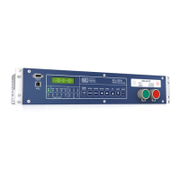
Relay models 0351Sxxx5/6/A/B feature auxiliary {TRIP} and {CLOSE}
pushbuttons and OPEN and CLOSED LED indicators. These features are
electrically isolated from the rest of the relay. They function independently
from the relay and do not need relay power.
The pushbuttons and LEDs can be hard-wired into a substation trip and close
control circuit and operate the same as a separate installation of external trip/
close switches and LED indicators. Figure 2.31 shows example trip and close
circuit connections for a control scheme configuration with a dc substation
voltage source. The pushbutton switches come set from the factory for dc
operation (arc suppression enabled). To use an ac trip or close potential, the
arc suppression must be disabled for one or both pushbuttons (see Table 2.10).
The voltage operating ranges of the LEDs are selected by jumpers (see
Table 2.9).
SEL-351S features such as Hot Line
Tag and Synchronism Check do not
supervise the auxiliary close
pushbutton.
Since the trip and close buttons are functionally separate from the relay, a
manual trip or close cannot be distinguished from an external protection or
automation-initiated operation. Unless provisions are made in the control
wiring, the action of the close pushbutton is unsupervised.


 To Next Page