2–10
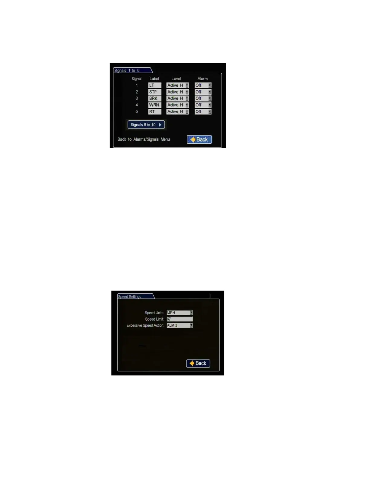
18. In the Alarms and Signals menu, click Signals.
The DVR signal harness has 5 dedicated signal input wire connections:
• LT - black wire
• STP - green wire
• BRK - red wire
• WRN - brown wire
• RT - white wire
19. In the Alarms and Signals menu, click Speed.
Label: For signals 1-5, labels are
provided for left turn, stop, brake,
warning light, and right turn. The
labels can be edited and changed,
maximum 3 characters. Signals 6-10
are available for advanced signal
wiring if required.
Level: Set all signal levels as required.
Choose Active High if the circuit you
are installing into rests at 0 VDC and
goes to 12 VDC when active. Choose
Active Low if the circuit rests at 12 VDC and drops to 0 VDC when active.
Alarm: Select the alarm number if the signal is also to be used to trigger an
alarm. That alarm’s input must also be set up in the Alarms menu.
Click Back to save the menu settings.
Figure 2-15
Signals 1 to 5 Menu
Speed Units
:
Choose MPH for US or
KPH for Canada.
Speed Limit
:
Enter the speed limit
which will trigger the excessive speed
alarm when exceeded.
Excessive Speed Action
:
Select the
alarm which will be triggered by
excessive speed.
Click Back to save the menu settings.
Figure 2-16
Speed Settings Menu
 Loading...