Do you have a question about the Sewhacnm SI 4100 and is the answer not in the manual?
Explains warning and caution symbols for user safety and product handling.
Details symbols related to electric shock, grounding, and operational prohibition.
States copyright information and provides contact details for product inquiries.
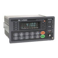
Introduces the SI 4100 Industrial Digital Weighing Controller and its capabilities.
Lists critical safety precautions for installation and operation to prevent damage or injury.
Highlights the main features and advanced functionalities of the SI 4100 controller.
Details technical specifications for analog signal input and analog-to-digital conversion.
Covers specifications for the digital display, status lamps, and keypad elements.
Provides overall specifications including power supply, operating conditions, and dimensions.
Lists the available option cards that can be installed in the controller.
Describes the front panel components including the display, weight unit, and keys.
Explains the meaning of various status lamps (ANNUNCIATORS) on the front panel.
Details the operation of individual keys (ZERO, TARE, T-RESET, RUN/STOP, HOLD/RESET, P/N, SUB, GRAND, CLEAR, ENTER, CAL) and combined key functions.
Describes the connectors and indicators located on the rear panel of the controller.
Provides detailed dimensions and cutting size requirements for panel mounting.
Lists the necessary components provided for the installation process.
Details the steps and guidelines for correctly installing the load cell.
Specifies the pinout and wiring for the load cell connector.
Provides important considerations for optimal load cell performance and accuracy.
Explains the formula required to ensure a precise weighing system configuration.
Explains the process of adjusting weight balance between the load cell and indicator.
Details the step-by-step calibration process using external test weights.
Explains how to calibrate the controller without using test weights.
Details how to enter the setup mode and change F-functions and their values.
Lists and describes various general function settings (F-functions) for controller configuration.
Explains how to configure relay outputs based on different weighing modes.
Details set value settings, relay delay times, and output logic for Limit Mode 1.
Details settings for Packer Mode, including relay outputs and the 'Drib' function.
Details set value settings, relay timing, and output logic for Comparison Mode.
Details set value settings and relay output logic for Packer Mode 2.
Details set value settings, relay delay times, and output logic for Limit Mode 2.
Details settings for user-configurable relay output sequences in Choice Mode 1.
Details settings for user-configurable relay output sequences in Choice Mode 2.
Details set value settings, control relay types, and output logic for Accumulating Mode 1.
Details settings for Packer Mode User's Choice 2, including relay outputs and 'Drib' function.
Details set value settings and relay output logic for Accumulating Mode 2.
Explains delay time (t1) and ON time (t2) settings for the FINISH relay.
Details the delay time (t3) for judging the 'STEADY' condition.
Explains the ON time (t4) setting for judging the 'STEADY' condition.
Details the application selection for the 'DRIB' control function.
Covers options for weight mode selection and manual discharge.
Details communication settings for Serial Port 1, including parity and speed.
Lists available serial communication speed options (bps).
Covers data transference methods, modes, formats, and byte selection.
Details print port selection and check-sum detection settings.
Explains serial port application selection and print mode configurations.
Details print format selections, language options, and paper withdraw rate.
Covers SUB/GRAND total data deletion and parallel port selection.
Explains function/clear key activation display and communication interval settings.
Details analog output selection, settings, and adjustment for 0-10V and 4-20mA.
Covers password usage, protocol frame transit, and BCD input type settings.
Explains EMPTY range settings, minimum, and maximum analog output adjustments.
Details the procedure for checking the span calibration value.
Covers checking and changing date/time, setting password, and version information.
Details communication settings for Serial Port 2, including parity and speed.
Lists available serial communication speed options (bps).
Covers data transference methods, modes, formats, and print settings.
Details the RS-232C serial interface, its communication methods, and signal format.
Explains communication procedures with PCs and external displays via RS-232C.
Explains the serial data format without transferring the ID number.
Details the serial data format including ID number and data transference.
Explains the CAS 22byte data format for serial interface.
Details the AD-4321 18byte data format for serial interface.
Describes the current loop interface for noise immunity and long-distance communication.
Shows the current loop circuit diagram and specifies its data format.
Details the pinout and wiring connections for the Centronics parallel interface.
Provides examples of print formats for single, continuous, sub-total, and grand-total data.
Details specifications, circuit diagram, and output adjustment for 0-10V analog output.
Shows the connector details for the analog output interface.
Details specifications, circuit diagram, and output adjustment for 4-20mA analog output.
Shows the connector details for the analog output interface.
Details the signal format for RS-422/485 serial interfaces.
Shows the RS-485 circuit diagram and refers to RS-232C for data format.
Details the F57-00 and F57-01 settings for BCD input.
Shows the F-function settings relevant to the BCD output interface.
Details the read commands used to retrieve data from the indicator.
Details the write commands used to control the indicator's functions.
Lists common errors related to load cell installation and their treatments.
Details errors that may occur during calibration and how to resolve them.
Lists specific indicator errors like 'CELL-Er' and 'Un-Pass' with their causes and treatments.
Explains the procedure to enter the indicator's test mode.
Describes the different test modes for checking indicator functions like A/D value, keys, relays, and communication.
Outlines the warranty period, exception clauses, and other related terms.
| Brand | Sewhacnm |
|---|---|
| Model | SI 4100 |
| Category | Controller |
| Language | English |