Doc# E145701 5 - 8
5: Communication Installation
Electro Industries/GaugeTech
The Leader In Power Monitoring and Smart Grid Solutions
Electro Industries/GaugeTech
The Leader In Power Monitoring and Smart Grid Solutions
The Unicom 2500 can be configured for either 4-
wire or 2-wire RS485 connections. Since the
Shark® 100/50 uses a 2-wire connection, you
need to add jumper wires to convert the Unicom
2500 to the 2-wire configuration. As shown in
Figure 5.7, you connect the “RX -” and “TX -”
terminals with a jumper wire to make the “-”
terminal, and connect the “RX +” and “TX +”
terminals with a jumper wire to make the “+”
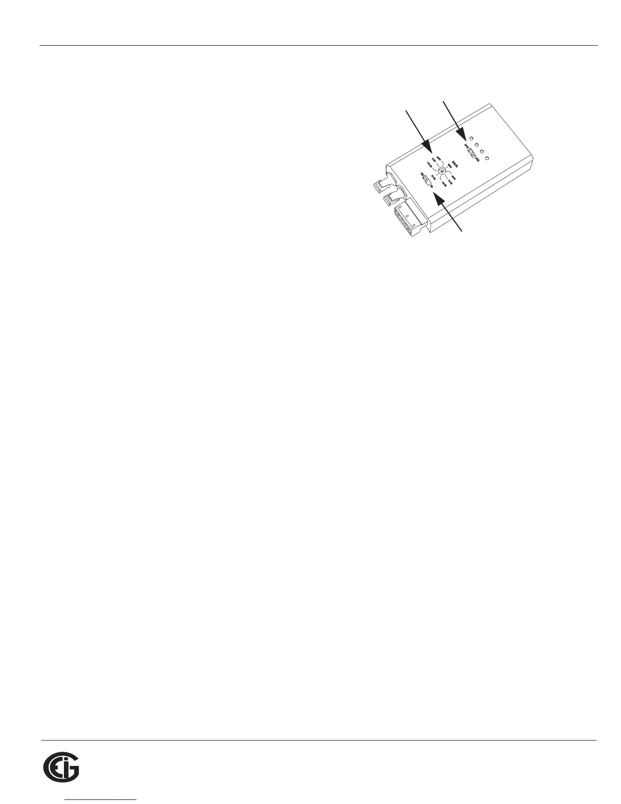
terminal. See the figure on the right for the Uni-
com 2500’s settings. The Unicom’s Baud rate
must match the Baud rate of the meter’s RS485 port: you set the Baud rate by turn-
ing the screw to point at the rate you want.
Baud Rate: 9600
Address: 001
Protocol: Modbus RTU
5.2: Configuring the Shark® 100 - INP10 Ethernet Connection
The INP10 option is the Ethernet option for the standard Shark® 100 meter. It allows
the Shark® 100 to communicate on a Local Area Network (LAN). The meter is easily
configured through a host PC using a Telnet connection. Once configured, you can
access the meter directly through any computer on your LAN.
NOTE: If you are using Windows 7 you need to enable Telnet before using it. See the
instructions on page 5-11.
This section outlines the procedures for setting up the parameters for Ethernet
communication:
• Host PC setup - Section 5.3.1
• Shark® meter setup - Section 5.3.2
v
Set switch
to DCE
Set the
Baud rate
Set switch
to HD