Doc# E145701 1-14
1: Three-Phase Power Measurement
Electro Industries/GaugeTech
The Leader In Power Monitoring and Smart Grid Solutions
Electro Industries/GaugeTech
The Leader In Power Monitoring and Smart Grid Solutions
harmonic distortion. Displacement power factor is calculated using the following
equation:
where T is the angle between the voltage and the current (see Fig. 1.9).
In applications where the voltage and current are not distorted, the Total Power Factor
will equal the Displacement Power Factor. But if harmonic distortion is present, the
two power factors will not be equal.
1.4: Harmonic Distortion
Harmonic distortion is primarily the result of high concentrations of non-linear loads.
Devices such as computer power supplies, variable speed drives and fluorescent light
ballasts make current demands that do not match the sinusoidal waveform of AC
electricity. As a result, the current waveform feeding these loads is periodic but not
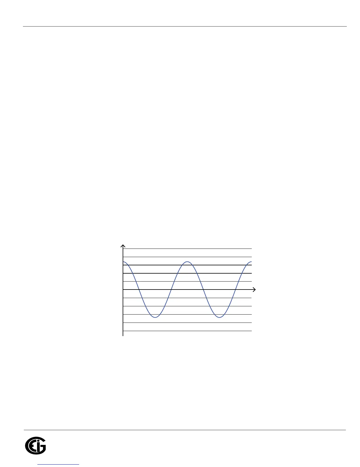
sinusoidal. Figure 1.10 shows a normal, sinusoidal current waveform. This example
has no distortion.
Figure 1.10: Nondistorted Current Waveform
Figure 1.11 shows a current waveform with a slight amount of harmonic distortion.
The waveform is still periodic and is fluctuating at the normal 60 Hz frequency.
However, the waveform is not a smooth sinusoidal form as seen in Figure 1.10.
Displacement PF Tcos=
Time
Amps
– 1000
– 500
0
500
1000