Main code Sub code Description Ref. Page
44 06 Compulsory execution of process control
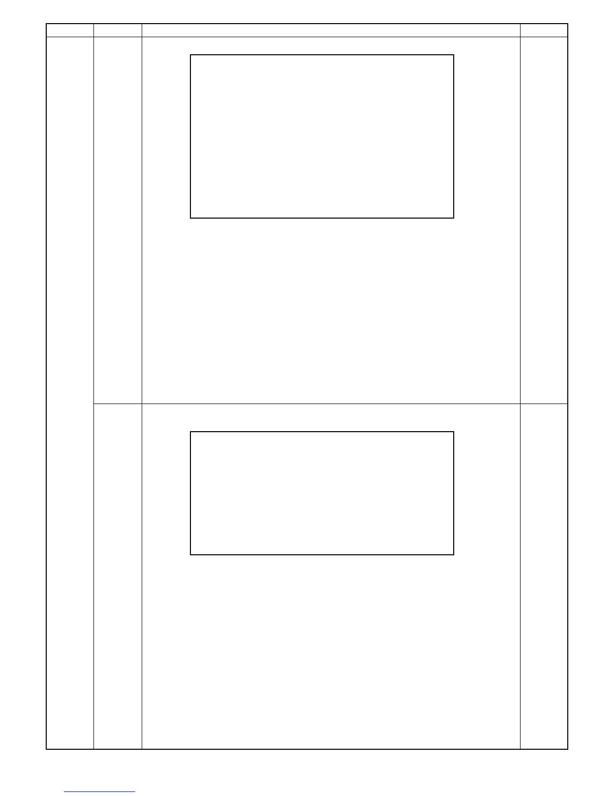
SIMULATION No.44-6
Process control execution
NORMAL : **** PATCH1 : ***
T/S : **** BASE1 : ***
PHOTO : **** PATCH2 : ***
GB ADJUST : *** BASE2 : ***
TARGET : *** PATCH3 : ***
ID GAIN : * BASE3 : ***
MARK : *** l: ***
MARK B : *** m: ***
DM GAIN : * n: ***
l*m*n: *** M1 : ***
M2 : ***
NORMAL : manual mode grid bias (350 ∼ 1150V)
T/S : Toner save mode grid bias (350 ∼ 1150V)
PHOTO
: Photo mode grid bias (350 ∼ 1150V)
GB ADJUST : Grid bias correction value after measurement (±0 ∼ 999V)
TARGET : Patch/surface. Patch reference value when surface is 255. (255 = Surface)
ID GAIN : Image density sensor gain rank in execution (1 ∼ 7)
MARK
: Drum mark sensor mark level in execution (0 ∼ 255 = 5V)
MARK B : Drum mark sensor surface level in execution (0 ∼ 255 = 5V)
DM GAIN : Drum mark sensor gain rank in execution (1 ∼ 7)
BASE 1,2,3 : Drum surface image density sensor level in execution (0 ∼ 255, 255 =5V)
PATCH123
: Toner patch image density sensor level in execution (0 ∼ 255, 255 =5V)
l : Vg correction coefficient
m : Dirt correction coefficient
n : Film wear correction coefficient
M1
: Dirt correction coefficient (M1)
M2 : Dirt correction coefficient (M2)
l*m*n : Vc1 correction coefficient
07 Drum mark sensor/image density sensor gain select check
The image density sensor level can be checked for selection of each gain rank. : 0~255, 255 = 5V
SIMULATION No.44-7
Gain select check of drum mark sensor
and image density sensor: 0 ∼ 255 (5V)
DM7 : *** ID7 : ***
DM6 : *** ID6 : ***
DM5 : *** ID5 : ***
DM4 : *** ID4 : ***
DM3 : *** ID3 : ***
DM2 : *** ID2 : ***
DM1 : *** ID1 : ***
Since the max. difference in amplifier rates between two gains is 132%, supposing the max. sensor
input is 4.8V, the gain rank is increased by +1 for 3.6V.
8 – 13