Main code Sub code Description Ref. Page
44 09 Process control data display
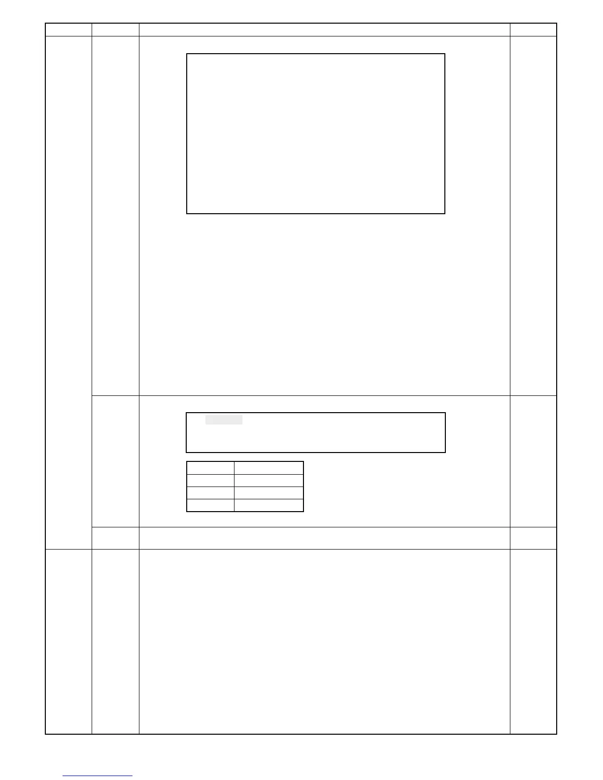
SIMULATION No.44-9
Process control data display
NORMAL : **** PATCH1 : ***
T/S : **** BASE1 : ***
PHOTO : **** PATCH2 : ***
GB ADJUST : *** BASE2 : ***
TARGET : *** PATCH3 : ***
ID GAIN : * BASE3 : ***
MARK : *** l: ***
MARK B : *** m: ***
DM GAIN : * n: ***
l*m*n: *** M1 : ***
M2 : ***
NORMAL : manual mode grid bias (350 ∼ 1150V)
T/S : Toner save mode grid bias (350 ∼ 1150V)
PHOTO
: Photo mode grid bias (350 ∼ 1150V)
GB ADJUST : Grid bias correction value after measurement (±0 ∼ 999V)
TARGET : Patch/surface. Patch reference value when surface is 255. (255 = Surface)
I D GAIN : Image density sensor gain rank in execution (1 ∼ 7)
MARK
: Drum mark sensor mark level in execution (0 ∼ 255 = 5V)
MARK B : Drum mark sensor surface level in execution (0 ∼ 255 = 5V)
DM GAIN : Drum mark sensor gain rank in execution (1 ∼ 7)
BASE 1,2,3 : Drum surface image density sensor level in execution (0 ∼ 255, 255 =5V)
PATCH123
: Toner patch image density sensor level in execution (0 ∼ 255, 255 =5V)
l : Vg correction coefficient
m : Dirt correction coefficient
n : Film wear correction coefficient
M1
: Dirt correction coefficient (M1)
M2 : Dirt correction coefficient (M2)
l*m*n : Vc1 correction coefficient
11 Enters the copy aging mode to allow the following operation and setting.
Display GB-350V GB_850V GB_1000V GB_1150V
PATCH : **** NORMAL : ***
T/S : **** PHOTO : ***
PATCH –630±10
NORMAL –860±10
T/S –755±10
PHOTO –610±10
Use "→" key to select, and press PSW to determine. Aging is started.
12 Copying is made without process control operation. This simulation is used to know whether the trouble
is in the process section or in the other section when F2 trouble occurs.
46 01
°
Exposure level adjustment
Used to adjust the copy density and the copy density select level. Refer to adjustment section page
7-19.
[7]-19-(6)
8 – 14