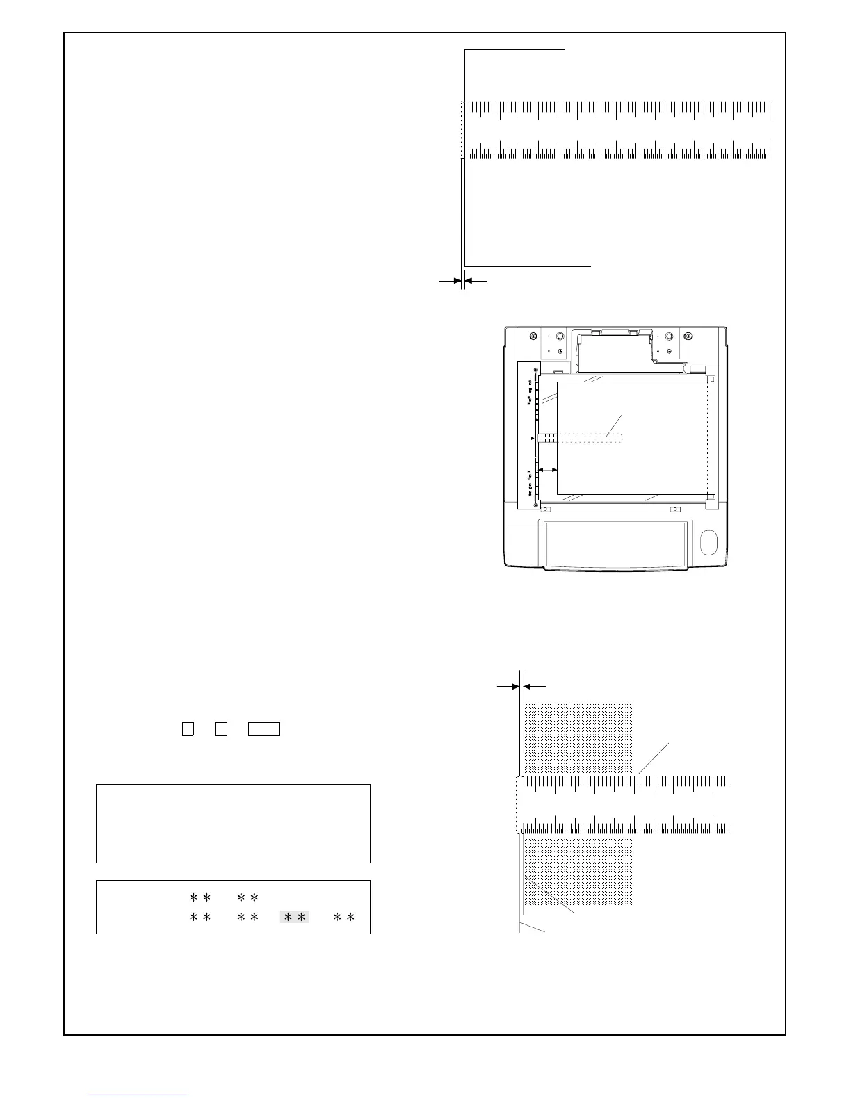
• L1: Lead edge deviation at 200% magnification
• L2: Lead edge deviation at 100% magnification
• RRC-A = 4.7222 x (L1 – L2)
• RRC-B = 7.2202 x L2 – 3.6101 x L1
5 Using the ten keys, input the values of RRC-A and RRC-B given
by the expressions shown above. For input procedure see 3).
6 Take copies at 200%, 100% and 50% magnification and check
the deviation difference at each magnification is less than ap-
prox. 1 mm.
If the difference is larger than 1 mm, repeat step 3 to 6.
7 Take a 100% copy to check the image loss for 4 mm or less. If
the image loss is larger than 4 mm, change the content of
RRC-B so that the range of the image loss is 3 mm or less.
Note: The image loss value adjusted as described above is
the image loss value adjusted in Simulation 50-01,
and not the final value.
8 Set a scale and an A3-size(11" x 17") blank paper on the
original table as shown in the figure.
9 Operate the scrol display key to set to the void adjustment mode
of the LCD.
F Take a copy. Type a value for adjusting the end void area of the
full-size copy so that, measured with the scale image, the solid
edge is 1 ~ 4 mm away from the paper end.
The key operation → → PSW provide a copy and sets
the input value. The input value of "1" corresponds to 0.2 mm in
void area. Larger input value provides larger void area.
10 20 30 40
50
60 70
Image loss
0~3mm
Full-size(100%) copy
10 20 30 40 50 60 70 80 90 50 100 110 120130 140
50mm
Scale
A3-size(11" x 17")
blank paper
10 20 30 40
50
end void area
1~3mm
Scale image
Solid edge
Paper end
Full-size(100%) copy
Simulation No. 50-1
1. Lead edge image position adjustment
2. Lead edge image position adjustment (Calculation formula)
MFT RRC VOIDA: B:
CS RRC
A: B: F: R:
7 – 16