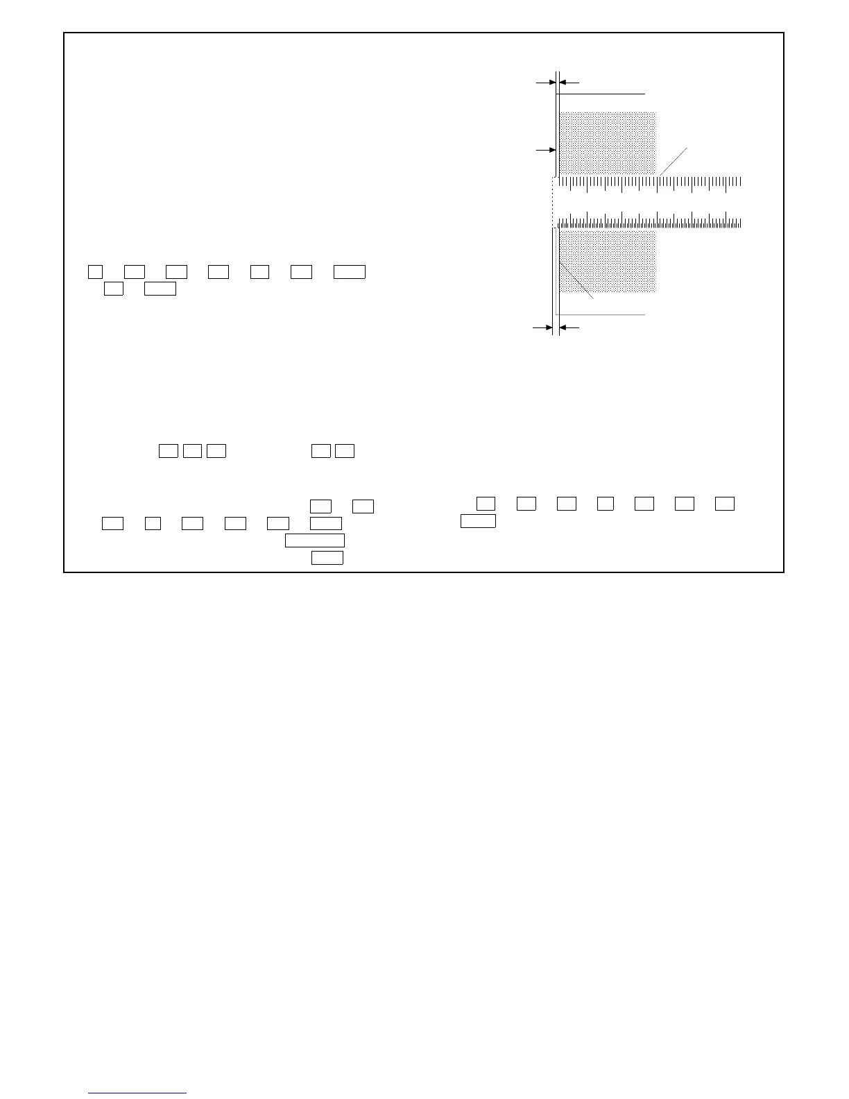
G Take a full-size copy and check if the image loss and the void
area meet the following standards:
(Standard value)
Image loss: 0 ~ 4 mm
Void area: 1 ~ 4 mm
H Press the clear key to clear Simulation 50-01.
Note: After changing the RRC-A and RRC-B settings, al-
ways adjust the void area of copy end.
(When using Simulation 50-02)
The key and indicator functions in Simulation 50-02 are the same
as those in Simulation 50-01.
Simulation 50-02 permits the values of L1 and L2 to be directly
input and the end adjustment to be easily performed.
Adjusting Procedure
1 Set a scale on the original table.
2 C → =↵ → 0/◊ → =↵ → 5 → 0/◊ → PSW
→ 2 → PSW to enter the Simulation 50-02 mode.
The machine starts warm-up operation.
3 Display example:
LEAD EDGE IMAGE POSITION ADJUSTMENT (CALCULATION FORMULA)
L1 L2: VOID:
• L1: Lead edge deviation at 200% magnification (FFF mm:
3-digit)
• L2: Lead edge deviation at 100% magnification (✕✕✕ mm:
3-digit)
Indication example of copy quantity indicator
42.5 mm → 4 2 5 → indicated as 2 5
4 Using the scrol display key and ten keys, set both A and B
values to 0 and take a copy at magnification 100% and 200%
respectively.
• An 100% copy can be taken by typing 0/◊ → 0/◊ →
0/◊ → ➡ → 0/◊ → 0/◊ → 0/◊ → PSW .
• A 200% copy can be taken by typing ENLARGE →
(After the lens moves, ready lamp ON) → PSW .
5 Measure the distance from the paper end to image(scale) end of
the 200% and 100% copy, and using the scrol display key and
the ten keys, type the L1 and L2 values. Type all three digits.
The RRC-A and RRC-B values of Simulation 50-01 are automat-
ically calculated and stored in memory.
Input Procedure
Assuming the L1 is 25.4 mm and L2 is 15.0 mm:
After checking that the last digit of the magnification indicator is
A, 2 → 5 → 4 → ➡ → 1 → 5 → 0 →
PSW .
6 Adjust and check the deviation, image loss and void area in the
same manner as in case of Simulation 50-01.
10 20 30 40
50
Void area
1~4mm
Paper end
Scale image
Solid edge
Image loss
0~4mm
Full-size(100%) copy
7 – 17