Introduction of Shihlin Inverter
Introduction of Inverter
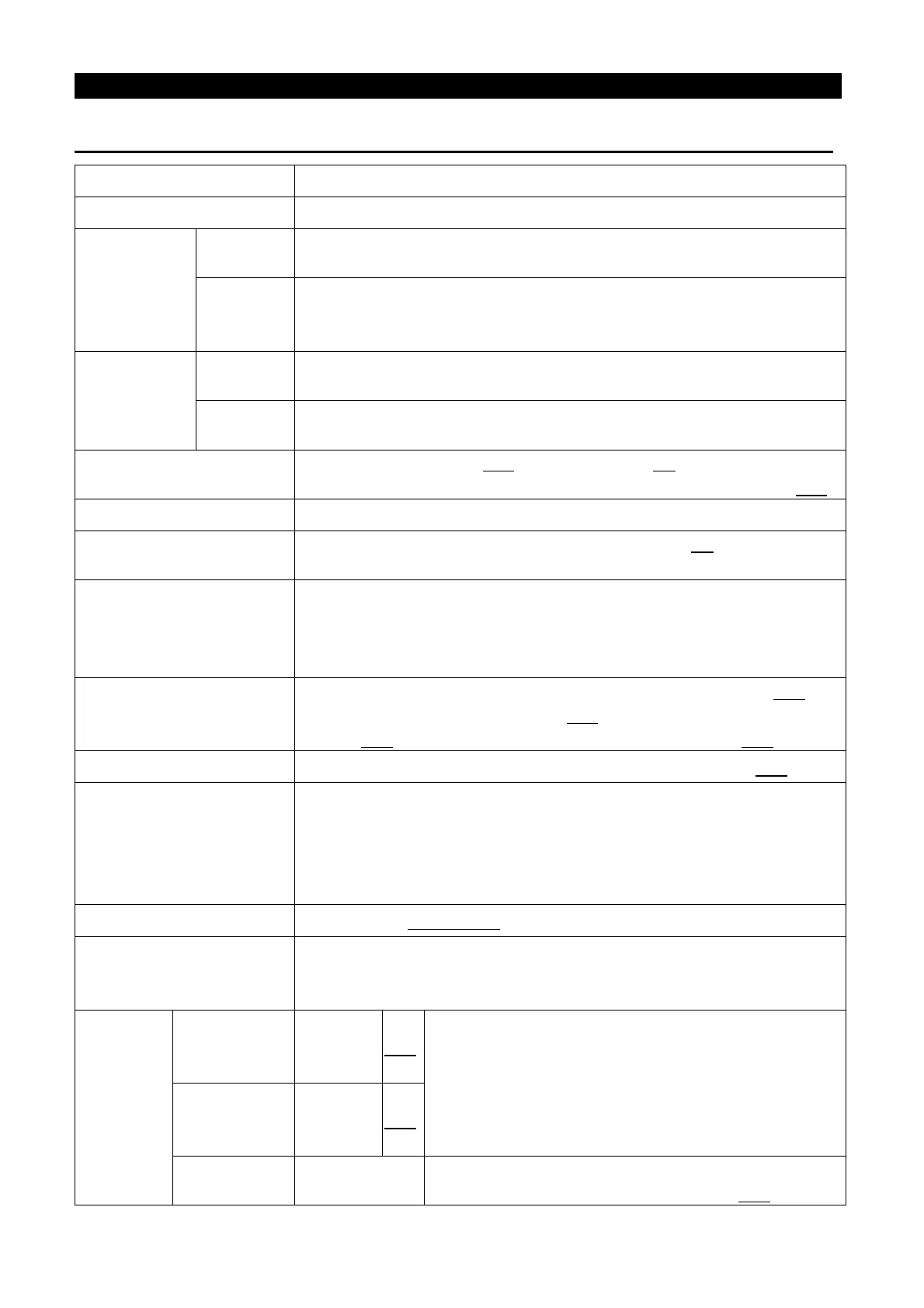
3.2 Common Specification (Inverter Characteristics)
Control Method SVPWM control, V/F control, general flux vector control.
Output Frequency Range 0. 1~650Hz (The starting frequency setting range between 0 and 60Hz).
Frequency
Resolution
Digital
setting
If the frequency value is set below 100Hz, the resolution will be 0.01Hz
If the frequency value is set above 100Hz, the resolution will be 0.1Hz.
Analog
setting
When setting the signal DC 0~5V, the resolution will be 1/500;
When setting the signal
DC 0~10V or 4~20mA, the resolution will be
1/1000.
Output
Frequency
Accuracy
Digital
setting
Maximum target frequency±0.01%.
Analog
setting
Maximum target frequency±0.5%.
Voltage / Frequency output
Characteristics
Base frequency voltage (P.19), base frequency (P.3) can be arbitrarily set.
Constant torque model and applicable load model can be selected (P.14).
Start Torque 150% 3Hz, 200% 5Hz: when using the facility vector control.
Torque Boost
The torque boost setting range between 0 and 30% (P.0
compensation.
Acceleration / Deceleration
Curve Characteristics
The resolution (0.01s/0.1s) of acceler
ation/deceleration time (P.7, P.8) is
switched by P.21. The setting range has 0~360s or 0~3600s
And different acceleration/deceleration curve model can be selected by
P.29.
DC Braking
The DC braking action frequency range between 0 and 120Hz (P.10
DC braking time is 0~60 Seconds (P.11
); and the DC braking voltage is
0~30% (P.12). Linear braking and idling braking selection (P.71).
Stalling Protection The stalling protection level can be set between 0 and 250% (P.22).
Target Frequency Setting
Operation panel setting;
DC 0~5V signal setting, DC 0~10V signal setting and DC 4~20mA
signal setting, two voltage input or one voltage and one current input
be selected, Multi-speed stage levels setting,
Communication setting.
PID Control Please refer to P.170~P.183 in Chapter 5.
Multifunction Control
Terminals
Motor starting (STF, STR), the second function (RT), ‘16-
operation’ (RL, RM, RH, REX), external thermal relay (OH), reset
(RES) , etc. (they can be set by the user with P.80~P.84, P.86)
Multi-functi
on Output
Terminals
Multi-function
output
terminals
SO,SE P.40
Inverter running (RUN), output frequency detection
(FU), Up to frequency (SU), overload detection (OL),
zero current detection (OMD), alarm (ALARM),
Section detection (PO1), Periodical detection (P
and Pause detection (PO3), Inverter output (BP),
Commercial power-supply output (GP).
Multi-function
output relay
A,B,C
P.85
Analog output
AM,5
Multi-function DC (0~10V)
Output: output frequency, output current (P.54).

 Loading...