Parameter Description
Parameter Description
107
This function is only for terminal. Near the lowest frequency or maximum frequency, output frequency
precision which relative to the input signal will reduce; avoid the use of requiring a tight frequency control.
5.38 Multi-Function Control-Terminal Input Positive/Negative Logic (P.87)
P.87 “Multi-Function Control-Terminal Input Positive/Negative Logic”
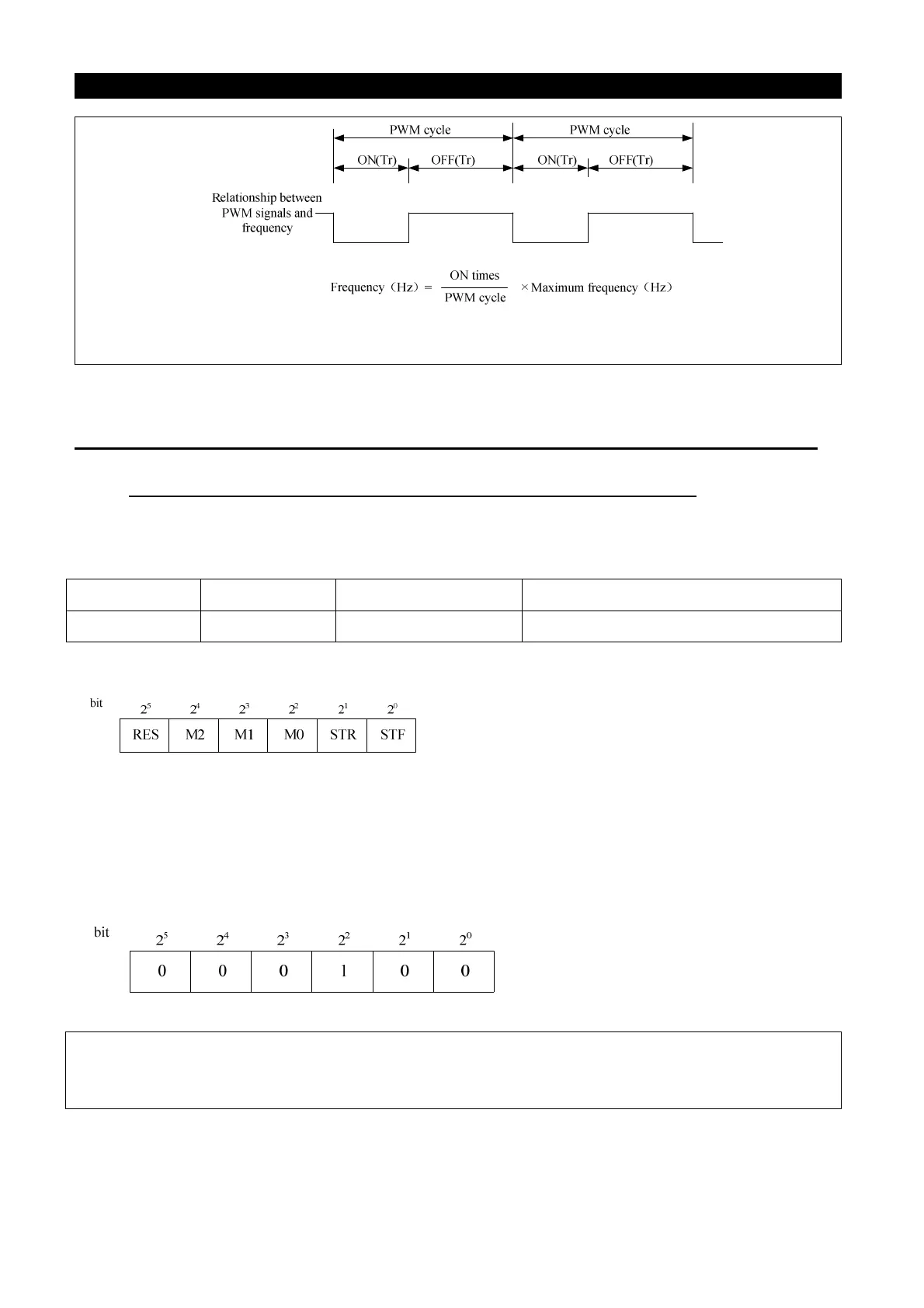
● The function is bits-setting, if the bits shows 1, it means that the act of multi-function control
terminal is negative logic; otherwise, it means that the act is positive logic.
Parameters Factory Setting
Setting Range Remarks
87 0 0~63 ---
The definiton of each P.87 bits are as follows :
For example : A three-wire control type needs the function of STOP to be kept open(negative logic).
So if set P.80=31, take M0 terminal as three-wire control STOP function, and P.83=0,P.84=1, and
take STF and STR terminals as default positive/negative logic function, the parameter of P.87 should
be setted as follows:
So P.87= 0×2
5
+ 0×2
4
+ 0×2
3
+ 1×2
2
+ 0×2
1
+ 0×2
0
= 4
Note: when multi-function control terminals select RES negative logic function, inverter will flicker
and display Err (equal to perform external RESET function), which can be cancelled just by
shorting-circuit SD and corresponding RES terminal, and inverter will work normally.

 Loading...