Parameter Description
Parameter Description
81
5.19 Voltage Signal Selection and Target Frequency (P.38, P.73, P.139~P.141)
P.38 “The maximum operation frequency (the target frequency is set by the input
signal of terminal 2-5)”
P.73 “Voltage signal selection”
P.139 “Voltage signal bias”
P.140 “Voltage signal gain”
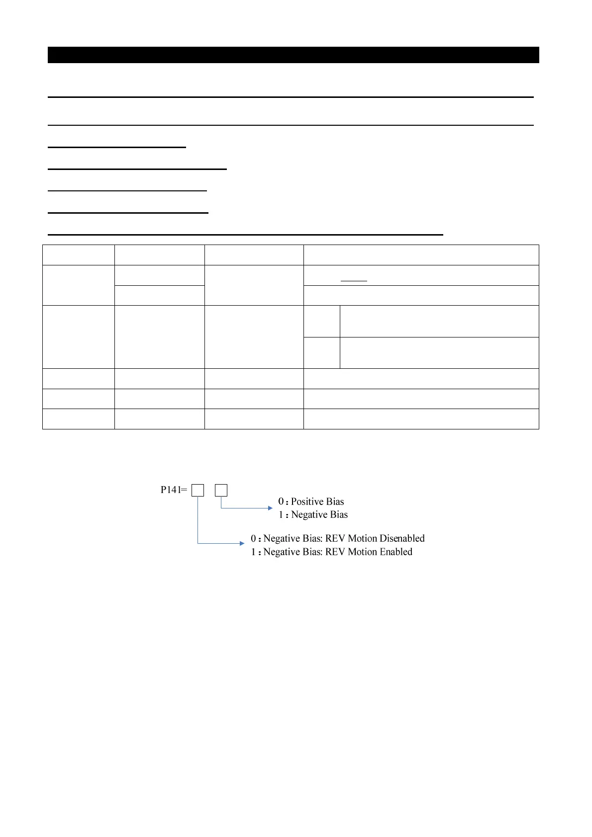
P.141 “Voltage signal bias direction and rotational direction setup”
Parameter Factory Setting
Setting Range Remarks
38
50Hz
1~650Hz
When P.189=1
60Hz When P.189=0
73 1 0, 1
0
The range for the input voltage signal
(terminal 2-5) is 0~5V.
1
The range for the input voltage signal
(terminal 2-5) is 0~10V.
139 0% 0%~200% ---
140 100% 0.1%~200% ---
141 0 0~11 ---
< Setting >
• P.141 has two digits, and each digit has its distinct meaning. Their relevant positions are presented
as follows:
• Set the frequency by using negative bias benefits to significantly avoid noise interference. In harsh
environments, the user is advised to avoid using the actuator signal, which is below 1V of the
operating frequency.

 Loading...