Parameter Description
Parameter Description
58
5.13 Acceleration/deceleration Curve Selection (P.29, P.255~P.258
P.29 “Acceleration/deceleration curve
selection”
P.255 “S pattern time at the beginning
of Acceleration”
P.256 “S pattern time at the end of
Acceleration”
P.257 “S pattern time at the beginning
of Deceleration”
P.258 “S pattern time at the end of
Deceleration”
<Setting>
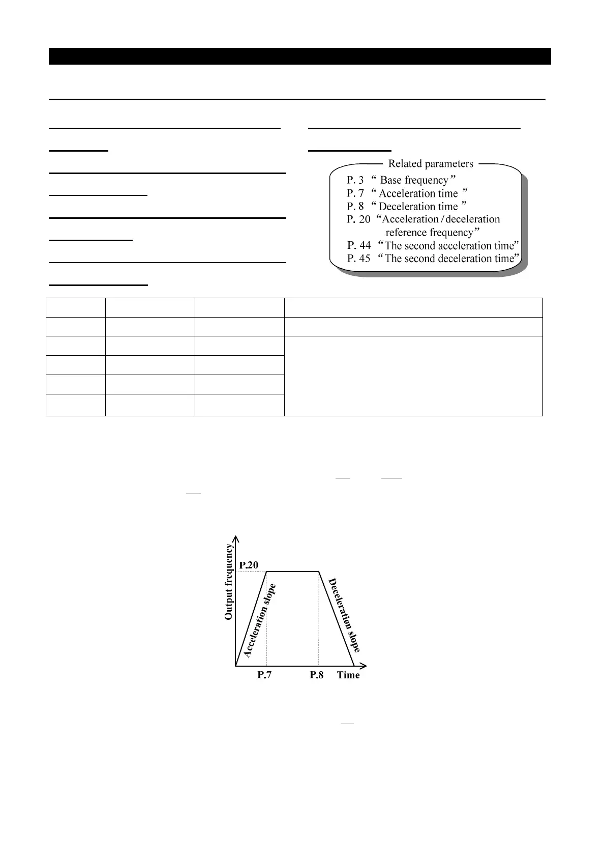
• The Linear acceleration/deceleration curve when P.29=0:
The acceleration slope is constructed by combining P.7 and P.20. The deceleration slope is
constructed by combining P.8 and P.20.
The target frequency increases and decreases linearly as the acceleration and the deceleration slopes
presented in the figure below.
• S-shape acceleration/deceleration curve 1 when P.29=1:
The acceleration slope is formed by combining P.7 and P3. The deceleration slope is formed by
combining P.8 and P.3.
The acceleration and deceleration curves are in an S-shape.
Parameter
Factory Setting
Setting Range Remarks
29 0 0~3 ---
255 0.2s 0~25s
They are vlid in the mode of S pattern
acceleration/deceleration mode (P.29=3)
to set the acceleration time of S pattern
acceleration/deceleration. If 9999 is set, the time
corresponds to the value of P.255.
256 9999 0~25s,9999
257 9999 0~25s,9999
258 9999 0~25s,9999

 Loading...