Parameter Description
Parameter Description
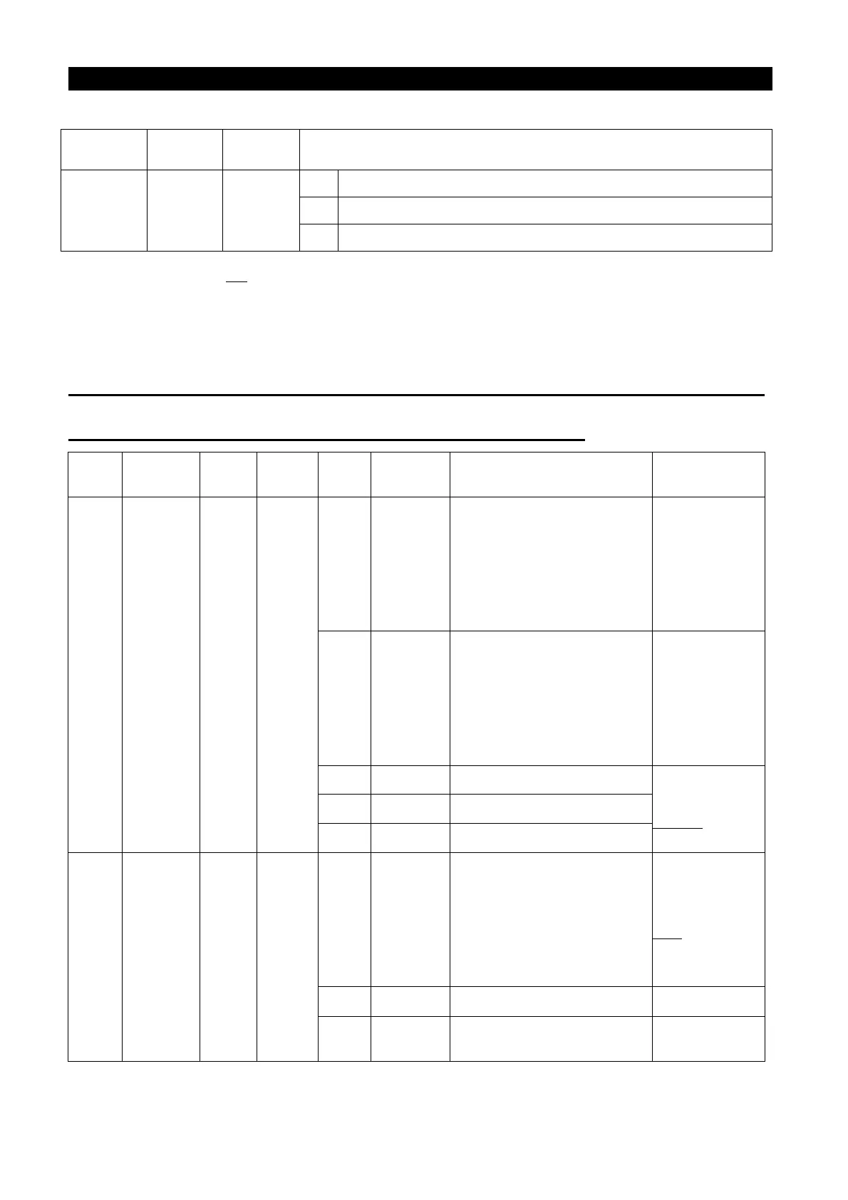
102
Parameter
Factory
Setting
Setting
Range
Remarks
79 0 0~8
6 Only the combined mode 3 is valid.
7 Only the combined mode 4 is valid.
8 Only the combined mode 5 is valid.
Please refer to Section 4.1 for details.
5.37 Multi-function Terminals Function Selection (P.80~P.84, P.86)
P.80~P.84, P.86 “Multi-function terminals function selection”
Para-
meter
Terminal
Setting
Setting
Range
Value
Function
Name
Function Description Remarks
80 M0 2
0~40
, 43~45
0 STF
At the external mode,
combined mode 1, or
combined mode 3, the
inverter runs forwards when
STF is on.
At the
programmed
it is used as a
start signal
terminal.
1 STR
At the external mode,
combined mode 1, or
combined mode 3, the
inverter runs reversely when
STF is on.
At the
programmed
it is used as a
pause signal
terminal.
2 RL Multi-speed
Please refer to
P.4~P.6
3 RM Multi-speed
4 RH Multi-speed
81 M1 3
0~40
, 43~45
5 AU
At the external mode,
combined mode 2 or
combined mode 4, the
inverter target frequency is
set by the signal input across
terminal 4-5 when AU is on.
Please refer to
P.39
6 OH (Note 3)
7 MRS
When MRS is turned on, the
output terminates.

 Loading...