Connection mod‐
ules
Interface Reference
CDB620-001 CAN see "Wiring the CAN interface in the CDB620-001",
page 79
CDM420-0001 CAN see "Wiring the CAN interface of the device in the
CDM420-0001", page 91
CDM420-0006 CAN see "Wiring the CAN interface of the device in the
CDM420-0006", page 103
NOTE
For further connection modules see
•
www.sick.com/CDB
•
www.sick.com/CDM
If the CAN interface is wired via a connection module, observe the respective operating
instructions of the module.
6.5.4 Wiring the digital inputs
Digital inputs can be used, for example, to start and end the reading pulse or to feed in
an increment signal.
Physical digital inputs on the device:
Table 10: Characteristic data of the digital inputs
Type Switching
Switching behavior Power to the input starts the assigned function, e.g., start of the
internal reading interval of the device.
Properties
•
Opto-decoupled, reverse polarity protected
•
Can be wired with PNP output of a trigger sensor
Electrical values The electrical values are identical for all digital inputs.
Low: |V
in
1)
| ≤ 2 V; |I
in
2)
| ≤ 0.3 mA
High: 6 V ≤ |V
in
| ≤ 32 V; 0.7 mA ≤ |I
in
| ≤ 5 mA
1)
Input voltage.
2)
Input current.
Signal 3
3.32K
6.64K
"
§
$
Sensor GND
V
S
2
V
S
V
S
V
in
5
!
PNP sensor 1
GND
Digital input 4
GND
V
S
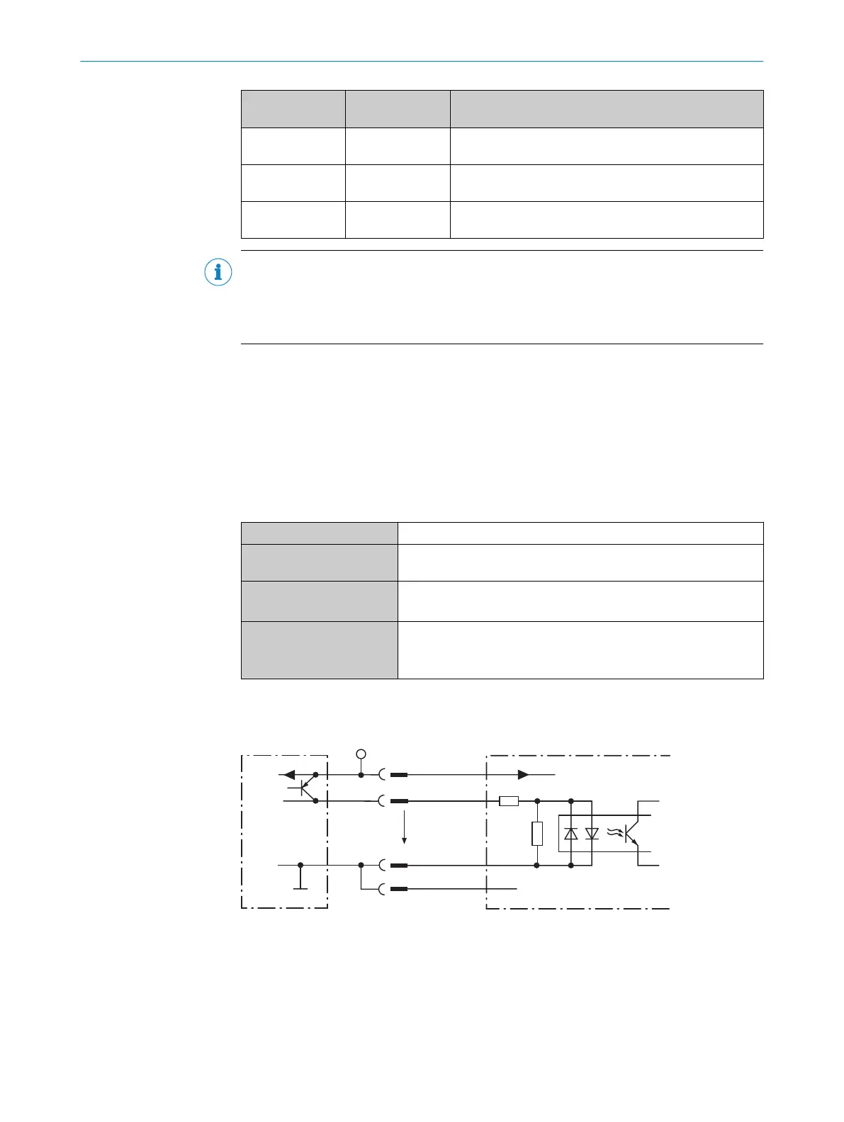
Figure 25: Wiring of a digital input on the device with external PNP sensor
1
PNP sensor
2
Supply voltage V
S
3
Input signal
4
Digital input
5
Input voltage V
in
!...$
For pin assignment, see respective device
ELECTRICAL INSTALLATION 6
8017840/19OF/2021-10-28 | SICK O P E R A T I N G I N S T R U C T I O N S | CLV61x
43
Subject to change without notice
 Loading...


