Operating Instructions Chapter 13
DME5000
8009813/ZJV1/2017-05 © SICK AG • Germany • Subject to change without notice 127
13.3 Commissioning DME5000 PROFIBUS
®
(Example Siemens Step 7)
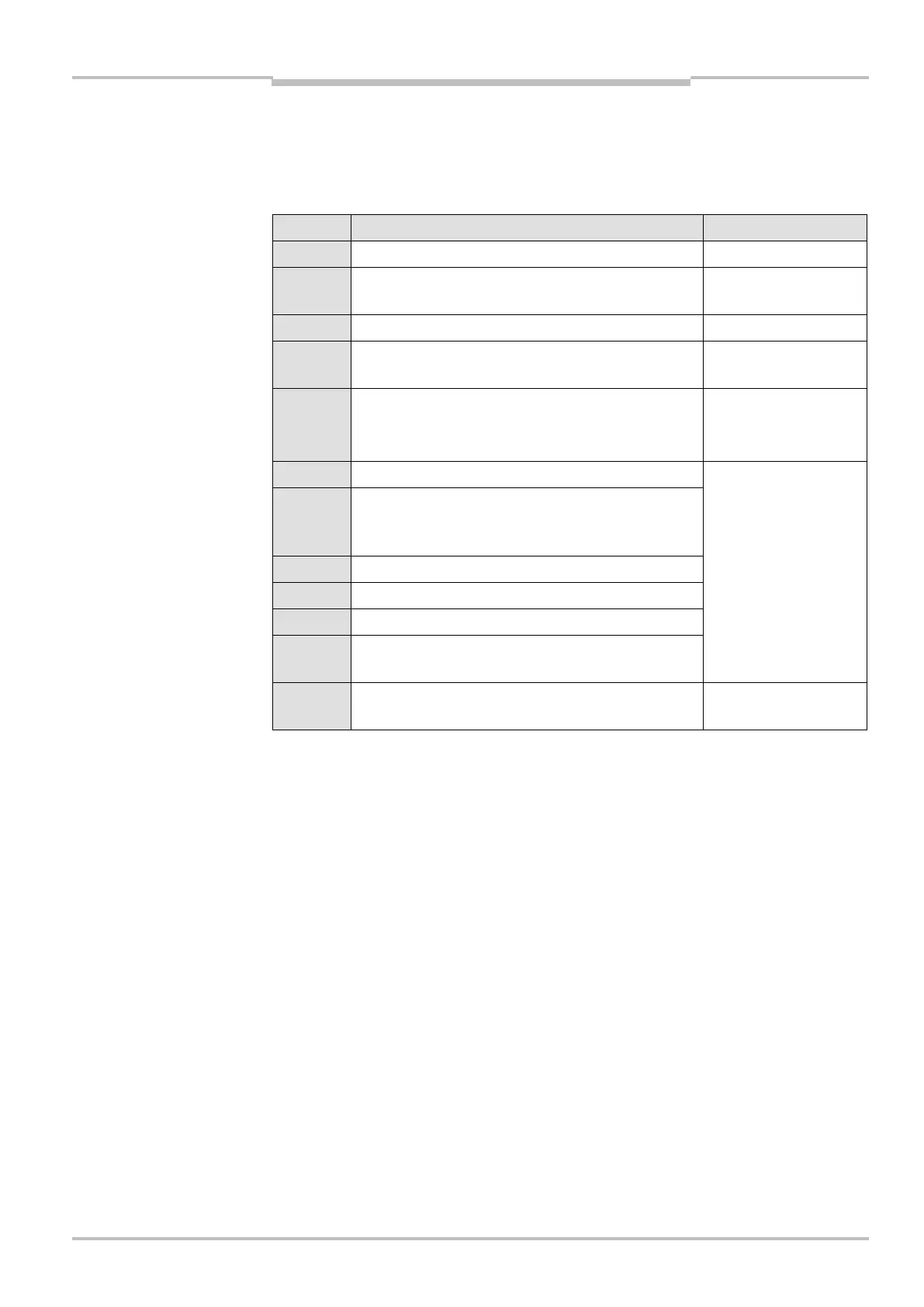
The example leads to the settings recommended in the annex PROFIBUS Profile. Also see
figure (screenshot).
Step Activity Chapter
1 Connect and plug on 8-pin device 5.2
2 Establish visual contact with reflector, set PROFIBUS
address (default 006) (menu item 3.1.2.)
7.2
3 Plug on 4-pin PROFIBUS-plug "Bus in" 5.2
4 Plug on 4-pin PROFIBUS-plug "Bus out"/or plug on
terminal resistor
5.2 or 5.2.2
5 Copy GSD file in the gsd directory
(:\siemes\step7\s7data\gsd)
(observe notes on gsd file in section 12.1.
Siemens
6 Update hardware catalogue Siemens
7 DME5000 PROFIBUS
in the hardware catalogue:
PROFIBUS-DP\weitere Feldgeräte\Encoder\
DME5000 PROFIBUS
®
8 DME5000
9 Selection - Class 2: 4-Byte-I/O
10 Assign E/A addresses (double-click E/A address)
11 Set parameters (double-click E/A address – menu
item "Parameterize")
12 GSD parameter "Extended diagnostics" disabled:
Do not send device-specific diagnosis data´
Annex PROFIBUS
Interface
When using the SICK profile, the double word can be pushed to the left with operation
SLD7 and then to the right with the operation SRD7 to separate the 7 diagnosis bits (bit
25 … 31) of measured value (bit 0 … 24). This replaces all 7 diagnosis bits by "0".
Note