Operating Instructions Chapter 5
DME5000
8009813/ZJV1/2017-05 © SICK AG • Germany • Subject to change without notice 79
5 Commissioning
5.1 Mounting
The DME5000 and the reflector are attached so that the reflector is always in the sensor's
field of view.
The DME5000 is aligned so that the light spot is well visible (even at large distances) at
the reflector's center.
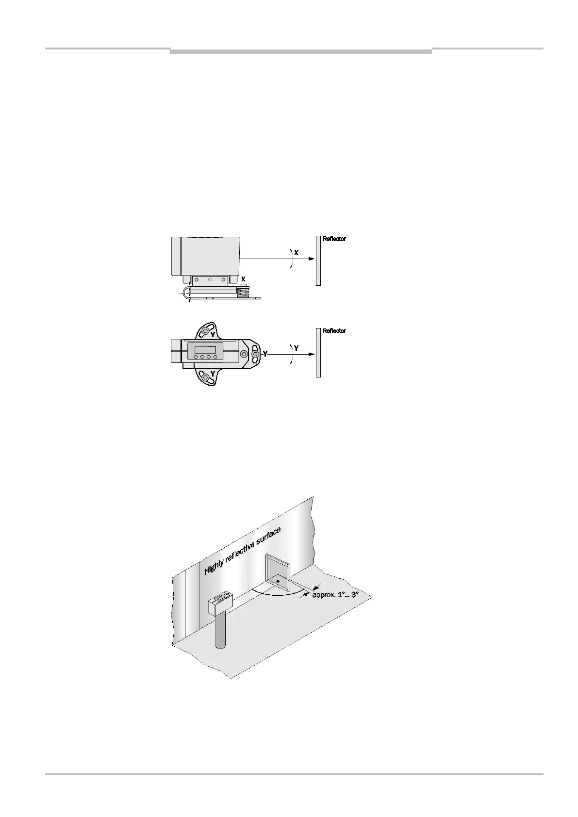
The alignment bracket, available as an accessory, enables easy alignment in X- and Y-
directions:
Select the reflector size so that the light spot does not move off of the reflector in case of
vibrations. If the reflector is attached to the moving part, a smaller reflective tape is usually
sufficient. If there are any highly reflective surfaces (e.g. shelf profiles, palettes wrapped
with stretch foil, rails) that reflect the light beam or stray light, the reflector must be
aligned into the "free space": mount with a tilt of approx. 1° … 3° (X- or Y-direction). For
different reflector sizes, see section 9.2 "Accessories" (page 102 and following)
Fig. 2: Alignment DME5000
Fig. 3: Alignment DME5000
in a highly reflective