3 SYSTEM DESCRIPTION
8023994-17I6/2020-03-19|SICK
ORIGINAL OPERATING INSTRUCTIONS| VMS4100/5100
Subject to change without notice
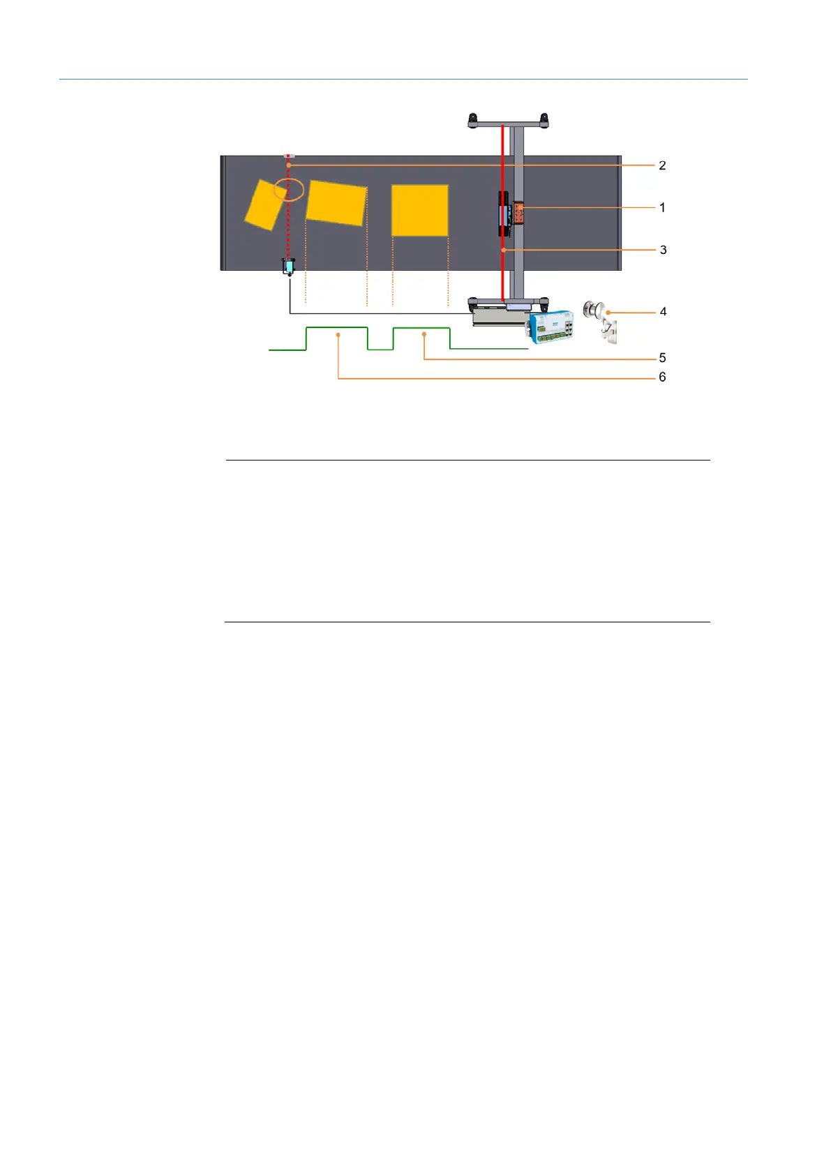
Fig. 10: Triggered mode
Legend
1 Measurement site
2 Trigger line of the photoelectric retro-reflective sensor
3 Scanning line of the 2D LiDAR sensor
4 Incremental encoder
5 Reading gate for triggered object 2
6 Reading gate for triggered object 1
• The object is detected by a trigger signal.
• The trigger signal can be triggered by the entry of the object into the path of
a photoelectric retro-reflective sensor or via a customer-controlled digital signal.
• The trigger signal activates the 2D LiDAR sensors and opens the internal reading gate.
• The reading gate determines the start and end of the measuring process.
It corresponds to the trigger length in the conveying direction.
• The measuring process lasts for as long as the reading gate is open, regardless
of whether the object is entering or leaving the scanning line.
• In both operating modes, the incremental encoder supplies information for defining
the exact position of the object on the conveying equipment.
• This information is required to calculate the length information and for correct
assignment of the measurement results to the object.
Triggered
mode
Object tracking
 Loading...


