ELECTRICAL INSTALLATION 5
8023994-17I6/2020-03-19|SICK
Subject to change without notice
ORIGINAL OPERATING INSTRUCTIONS| VMS4100/5100
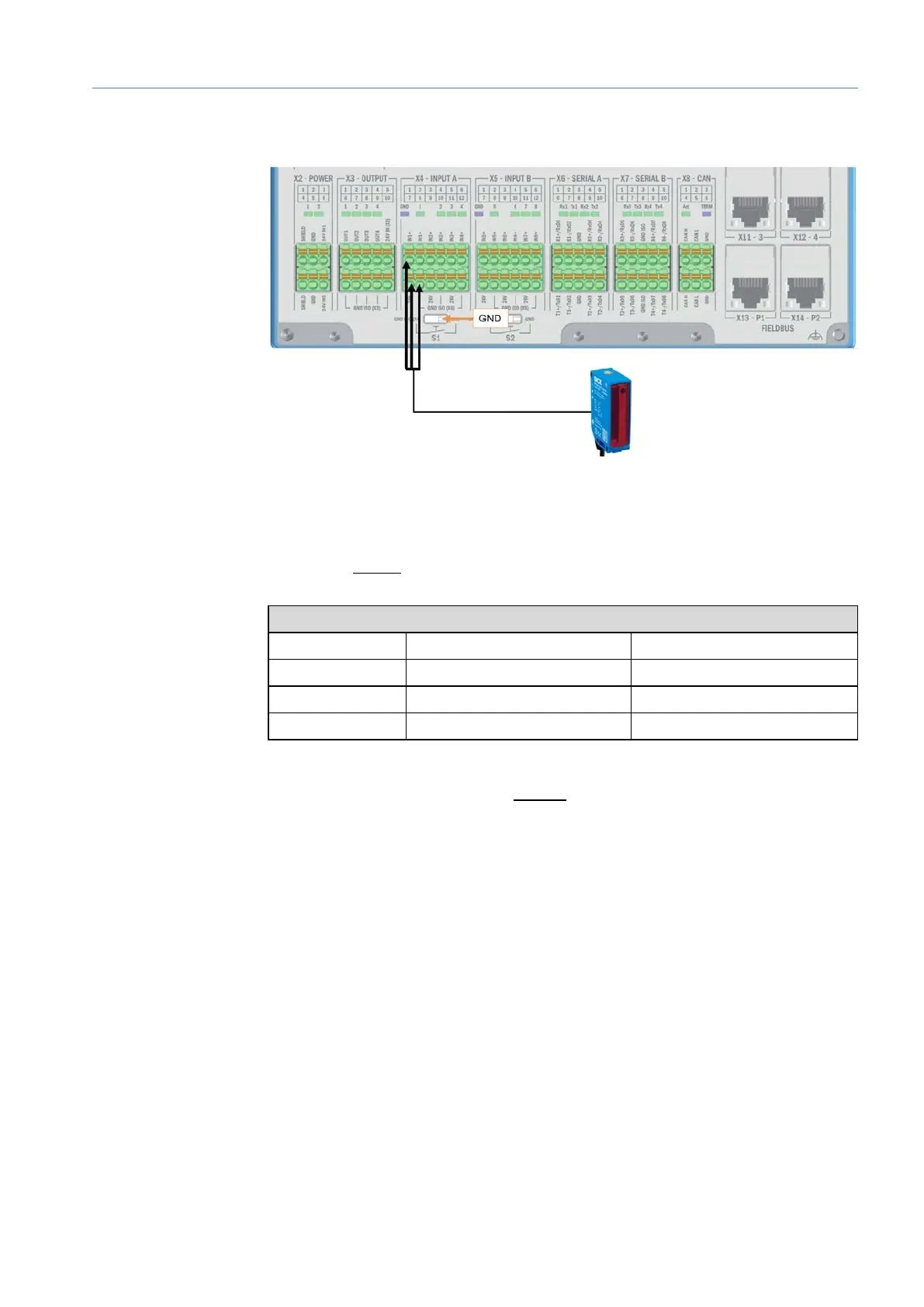
5.7 Connection for the photoelectric retro-reflective sensor trigger (optional)
Fig. 82: Connection for the photoelectric retro-reflective sensor trigger (optional)
• Connecting cable included in scope of delivery.
• M12 plug connector for connecting to the photoelectric retro-reflective sensor.
• Open end without shielding for connection to the SIM2000.
Trigger signal
Wire color Terminal Connection
Black X4 INPUT A 1 IN1+
Brown X4 INPUT A 7 24 V
Blue X4 INPUT A 8 GND ISO (X4)
Tab. 16: Connection for the photoelectric retro-reflective sensor trigger (optional)
• If the trigger signal comes from an external source, the switching input can be
connected to the controller in a volt-free manner.
• In this case, the DIP switch S1 must be set to GND_ISO (X4).
• The connection with terminal 7 (24 V) can be omitted.
Cable
Connection
External
trigger signal

 Loading...


