ELECTRICAL INSTALLATION 5
8023994-17I6/2020-03-19|SICK
Subject to change without notice
ORIGINAL OPERATING INSTRUCTIONS| VMS4100/5100
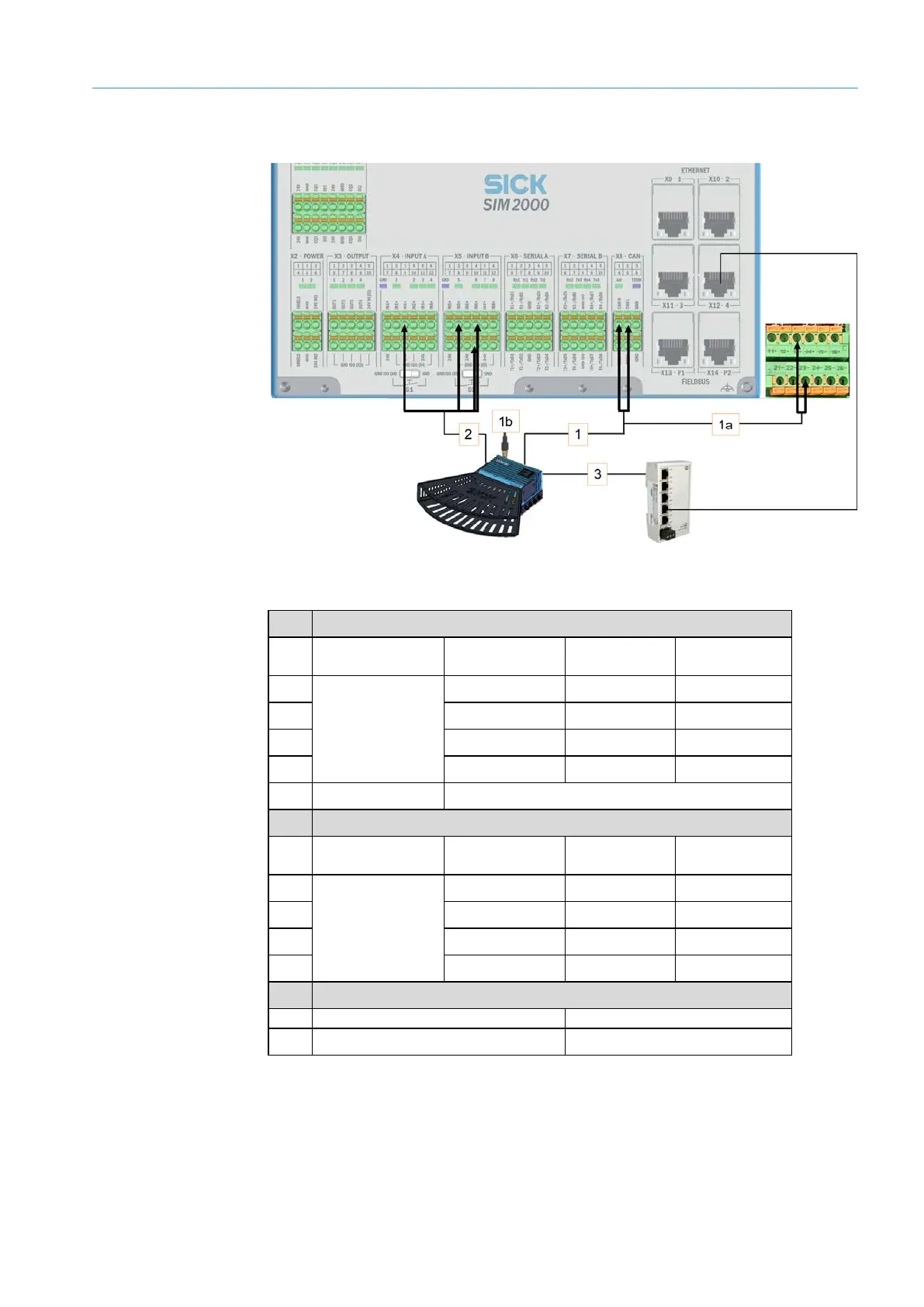
5.4.2 Cabinet with Ethernet switch
Fig. 78: Connection for the 2D LiDAR sensor on the SIM2000 system controller / Ethernet switch
1 CAN bus/voltage supply
Connection for
Wire color SIM2000
Connection
POWER CAN_IN
White X8 CAN 1 CAN_H
Blue X8 CAN 2 CAN_L
1a Red F1_6A 13 +
Black F1_6A 23 -
1b Power CAN_OUT Terminator
2 Increment
Connection for
the LMS4x21
TACHO INPUT
Gray X4 INPUT A 3 IN2+
White X5 INPUT B 2 IN5+
Black X5 INPUT B 4 IN6+
Blue X5 INPUT B GND ISO (X5)
3 Ethernet
Connection for the LMS4x21
Ethernet 1
Tab. 12: Connection for the 2D LiDAR sensor on the SIM2000 system controller / Ethernet switch
 Loading...


