ELECTRICAL INSTALLATION 5
8023994-17I6/2020-03-19|SICK
Subject to change without notice
ORIGINAL OPERATING INSTRUCTIONS| VMS4100/5100
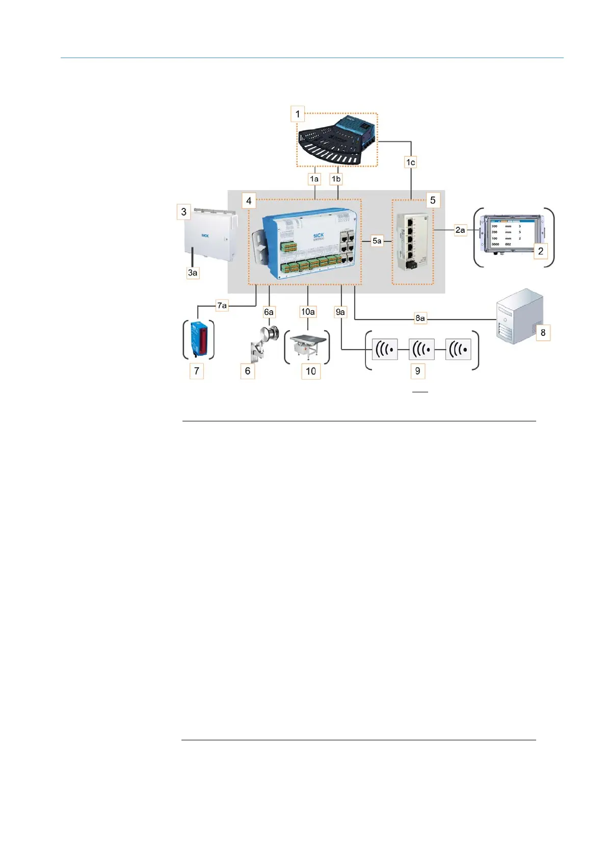
5.1.2 Cabinet with Ethernet switch
Fig. 74: Connection overview for VMS4100/5100 - cabinet with Ethernet switch
1a CAN bus
LFT display - VMS5100 only
3 Cabinet
Feed 100 ... 264 V AC / 50 ... 60 Hz
SIM2000 system controller
6 Incremental encoder
Photoelectric retro-reflective sensor (optional)
8a Data output via Ethernet, fieldbus, or serial connection
Reading station (optional)
Weighing station (optional)
Data connection
 Loading...


