SYSTEM DESCRIPTION 3
8023994-17I6/2020-03-19|SICK
Subject to change without notice
ORIGINAL OPERATING INSTRUCTIONS| VMS4100/5100
3.8.5 Test instructions for market surveillance
This chapter describes the procedure for inspecting the certified VMS5100 measurement
system with regard to:
• The performance of metrological measurements with defined test objects and the
display of the measurement results on the LFT display.
• The display of data sets stored in the alibi memory on the LFT display.
• The display of system component firmware versions via the LFT display.
▸
Establish the voltage supply to the devices via the power supply unit in the cabinet.
• All system components start up automatically and are then ready for use.
• The MEASUREMENT tab is active in the menu bar. No measured values are available
yet.
▸
Measure test objects made from a dimensionally stable material of various shapes
and surface qualities.
▸
Perform measurements in free-running or triggered mode depending on the operating
mode (see chapter 3.3 Triggering the recording of measured values).
NOTE! The nominal dimensions (length, width, height) must cover approximately 90%,
50%, and 10% of the total measuring range for each dimension. The actual dimensions
must not be less than the minimum dimensions or exceed the maximum dimensions
specified for the VMS5100.
▸
Make sure that the required distances between the test objects are maintained
depending on the operating mode(see chapter 3.4 Operating modes).
▸
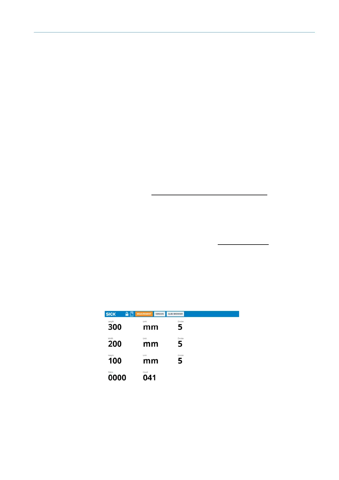
Compare the actual values for each measured test object with the dimensional values
on the LFT display.
NOTE!
• Valid measurement results have the status 0 0 0 0. They are LFT-verified and can
be used for billing.
• The Refresh Counter display (041 in the image below) is not legally relevant and
therefore not included in the alibi data.
Starting the
system
Measuring
test objects

 Loading...

