MOUNTING 4
8023994-17I6/2020-03-19|SICK
Subject to change without notice
ORIGINAL OPERATING INSTRUCTIONS| VMS4100/5100
4.3 Mounting the photoelectric retro-reflective sensor trigger (optional)
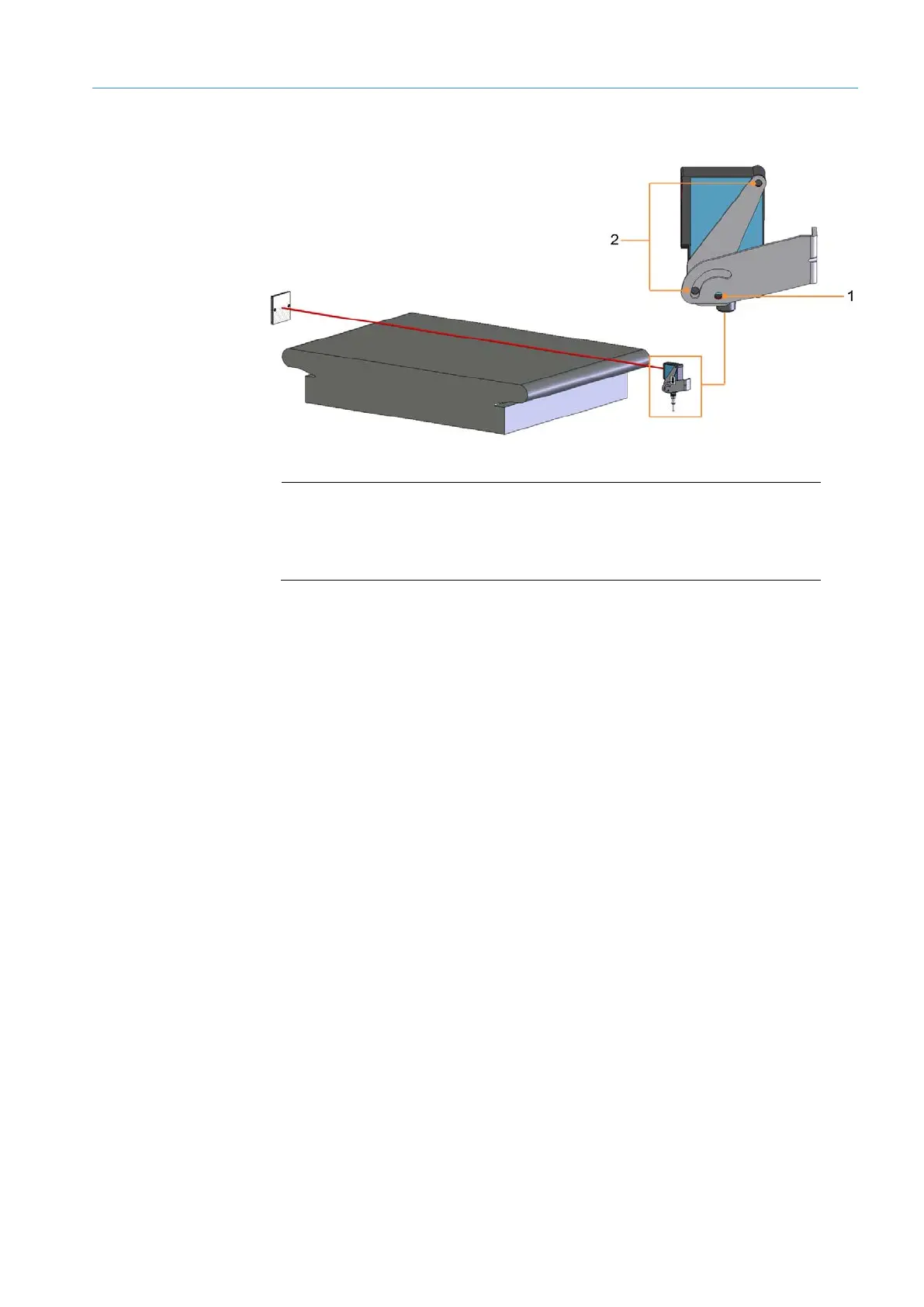
Fig. 71: Mounting the object detection photoelectric sensor
Legend
1 Clinch stud. Secures the object detection photoelectric sensor to the
mounting bracket.
2 M5 hexagon screws
▸
Mount the object detection photoelectric sensor on the mounting bracket using the
two M5 hexagon screws.
▸
Secure the photoelectric sensor using the clinch stud.
▸
Align the photoelectric sensor correctly on the reflector. The reflector must be
positioned within the beam path of the object detection photoelectric sensor.
Mounting

 Loading...


